REAR SUSPENSION MEMBER (for 2WD) INSTALLATION

-
INSTALL HOLE PLUG
-
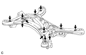
Install the 12 hole plugs to the rear suspension member sub-assembly as shown in the illustration.
Tech Tips
The upper and lower suspension member hole plug shapes are different.
-
-
INSTALL REAR SUSPENSION MEMBER FRONT BODY MOUNTING CUSHION (for LH Side)
-
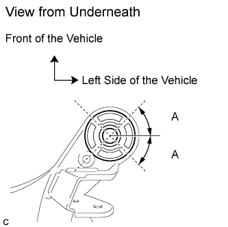
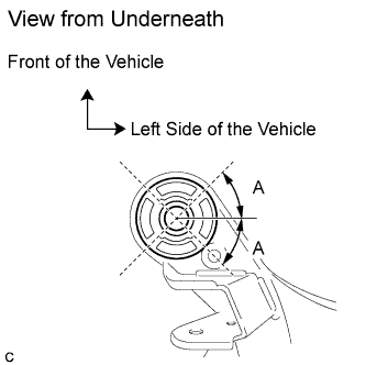
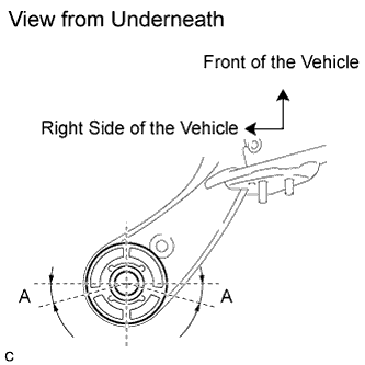
Temporarily install the rear suspension member front body mounting cushion (LH Side) while confirming the installation direction.
Standard (A) 40° to 50° -
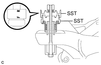
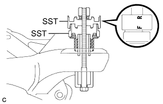
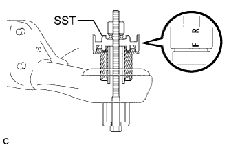
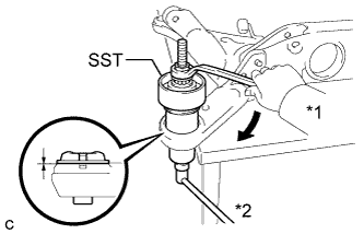
Install SST as shown in the illustration.
- SST
- 09527-17011
- 09830-10010 ( 09830-01010, 09830-01020, 09830-01030, 09830-01060 )
Note
Apply a small amount of grease to the threads and tip of SST (center bolt) before use.
Tech Tips
Use SST with the "F" mark facing the rear suspension member front body mounting cushion.
-
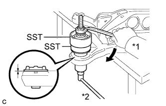
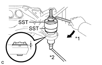
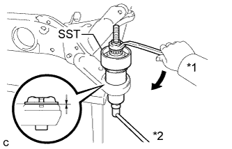
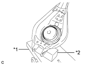
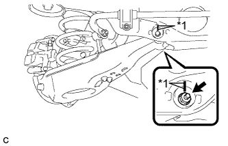
Text in Illustration *1 Turn *2 Hold Using SST, install the rear suspension member front body mounting cushion (LH Side) until there is no clearance between the rear suspension member sub-assembly and the rear suspension member front body mounting cushion (LH Side).
- SST
- 09527-17011
- 09830-10010 ( 09830-01010, 09830-01020, 09830-01030, 09830-01060 )
Note
If the rear suspension member sub-assembly is scratched, apply paint to the scratched areas of the rear suspension member sub-assembly.
-
Remove SST from the rear suspension member sub-assembly.
-
-
INSTALL REAR SUSPENSION MEMBER FRONT BODY MOUNTING CUSHION (for RH Side)
-
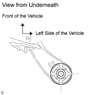
Temporarily install the rear suspension member front body mounting cushion (RH Side) while confirming the installation direction.
Standard (A) 40° to 50° -
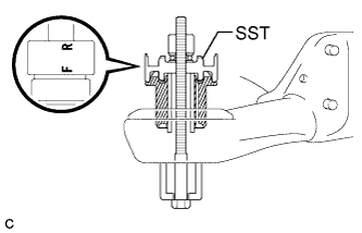
Install SST as shown in the illustration.
- SST
- 09527-17011
- 09830-10010 ( 09830-01010, 09830-01020, 09830-01030, 09830-01060 )
Note
Apply a small amount of grease to the threads and tip of SST (center bolt) before use.
Tech Tips
Use SST with the "F" mark facing the rear suspension member front body mounting cushion.
-
Text in Illustration *1 Turn *2 Hold Using SST, install the rear suspension member front body mounting cushion (RH Side) until there is no clearance between the rear suspension member sub-assembly and the rear suspension member front body mounting cushion (RH Side).
- SST
- 09527-17011
- 09830-10010 ( 09830-01010, 09830-01020, 09830-01030, 09830-01060 )
Note
If the rear suspension member sub-assembly is scratched, apply paint to the scratched areas of the rear suspension member sub-assembly.
-
Remove SST from the rear suspension member sub-assembly.
-
-
INSTALL REAR SUSPENSION MEMBER REAR BODY MOUNT CUSHION LH
-
Temporarily install the rear suspension member rear body mounting cushion LH while confirming the installation direction.
-
Install SST as shown in the illustration.
- SST
- 09830-10010 ( 09830-01010, 09830-01020, 09830-01030, 09830-01060 )
Note
Apply a small amount of grease to the threads and tip of SST (center bolt) before use.
Tech Tips
Use SST with the "F" mark facing the rear suspension member rear body mounting cushion.
-
Text in Illustration *1 Turn *2 Hold Using SST, install the rear suspension member rear body mounting cushion LH until there is no clearance between the rear suspension member sub-assembly and the rear suspension member rear body mounting cushion LH.
- SST
- 09830-10010 ( 09830-01010, 09830-01020, 09830-01030, 09830-01060 )
Note
If the rear suspension member sub-assembly is scratched, apply paint to the scratched areas of the rear suspension member sub-assembly.
-
Remove SST from the rear suspension member sub-assembly.
-
-
INSTALL REAR SUSPENSION MEMBER REAR BODY MOUNT CUSHION RH
-
Temporarily install the rear suspension member rear body mounting cushion RH while confirming the installation direction.
Standard (A) 10° to 20° -
Install SST as shown in the illustration.
- SST
- 09830-10010 ( 09830-01010, 09830-01020, 09830-01030, 09830-01060 )
Note
Apply a small amount of grease to the threads and tip of SST (center bolt) before use.
Tech Tips
Use SST with the "F" mark facing the rear suspension member rear body mounting cushion.
-
Text in Illustration *1 Turn *2 Hold Using SST, install the rear suspension member rear body mounting cushion RH until there is no clearance between the rear suspension member sub-assembly and the rear suspension member rear body mounting cushion RH.
- SST
- 09830-10010 ( 09830-01010, 09830-01020, 09830-01030, 09830-01060 )
Note
If the rear suspension member sub-assembly is scratched, apply paint to the scratched areas of the rear suspension member sub-assembly.
-
Remove SST from the rear suspension member sub-assembly.
-
-
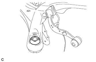
INSTALL REAR UPPER CONTROL ARM ASSEMBLY LH
-
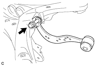
Temporarily install the rear upper control arm assembly LH to the rear suspension member sub-assembly with the bolt and nut.
Note
-
Insert the bolt with the threaded end facing the rear side of the vehicle.
-
Since the stopper nut is used, tighten the bolt.
-
-
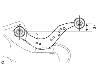
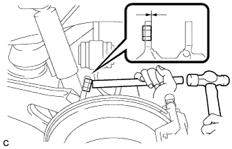
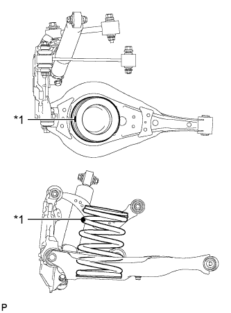
Set the rear upper control arm assembly LH in the tightening position as shown in the illustration.
Standard Length (A) 24.3 mm (0.957 in.) -
Fully tighten the bolt in the tightening position.
- Torque:
- 120 N*m { 1224 kgf*cm, 89 ft.*lbf }
Note
Since the stopper nut is used, tighten the bolt.
-
-
INSTALL REAR UPPER CONTROL ARM ASSEMBLY RH
Tech Tips
Perform the same procedure as the LH side.
-
INSTALL REAR SPEED SENSOR WIRE LH
-
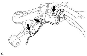
Install the rear speed sensor wire LH with the 2 bolts and nut as shown in the illustration.
- Torque:
- Bolt
- 8.0 N*m { 82 kgf*cm, 71 in.*lbf }
- Nut
- 9.0 N*m { 92 kgf*cm, 80 in.*lbf }
Note
Do not twist the rear speed sensor wire when connecting it.
-
-
INSTALL REAR SPEED SENSOR WIRE RH
-
Install the rear speed sensor wire RH with the 2 bolts and nut as shown in the illustration.
- Torque:
- Bolt
- 8.0 N*m { 82 kgf*cm, 71 in.*lbf }
- Nut
- 9.0 N*m { 92 kgf*cm, 80 in.*lbf }
Note
Do not twist the rear speed sensor wire when connecting it.
-
-
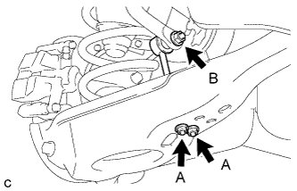
INSTALL REAR HEIGHT CONTROL SENSOR SUB-ASSEMBLY RH (w/ HID Headlight System)
-
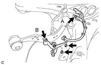
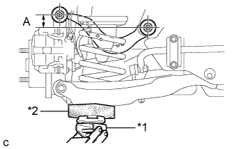
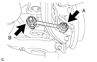
Install the rear height control sensor sub-assembly RH to the rear suspension member sub-assembly with the bolt (A) and 2 nuts.
- Torque:
- 5.0 N*m { 51 kgf*cm, 44 in.*lbf }
Note
Do not twist the rear height control sensor wire when connecting it.
-
Install the rear height control sensor sub-assembly RH to the rear upper control arm assembly RH with the bolt (B).
- Torque:
- 5.4 N*m { 55 kgf*cm, 48 in.*lbf }
-
-
INSTALL REAR SUSPENSION MEMBER UPPER STOPPER
-
Install the 2 rear suspension member upper stoppers as shown in the illustration.
Note
Be sure to install the rear suspension member upper stoppers in the correct direction shown in the illustration.
-
-
INSTALL REAR SUSPENSION MEMBER REAR UPPER STOPPER
-
Install the 2 rear suspension member rear upper stoppers as shown in the illustration.
-
-
INSTALL REAR SUSPENSION MEMBER SUB-ASSEMBLY
-
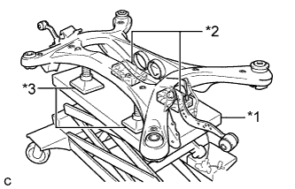
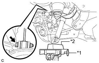
Text in Illustration *1 Jack *2 Wooden Block *3 Attachment Support the rear suspension member with a jack using 2 wooden blocks and 2 attachments or equivalent tools as shown in the illustration.
Note
Make sure to secure the rear suspension member to prevent it from dropping.
Tech Tips
Keep the suspension member level.
-
Raise the rear suspension member until there is no clearance between the rear suspension member and the body.
Note
-
When raising the rear suspension member, be careful not to damage the vehicle body or other components installed on the vehicle.
-
Keep supporting the rear suspension member until the installation has been completed.
-
-
Temporarily tighten the rear No. 1 suspension arm assembly LH.
-
Text in Illustration *1 Jack *2 Wooden Block Using a jack and wooden block, jack up the rear axle assembly LH to replicate standard vehicle height conditions.
-
Temporarily tighten the rear No. 1 suspension arm assembly LH to the rear axle carrier sub-assembly LH with the spacer and nut (A).
Note
Fully tighten the nut (A) after stabilizing the suspension.
-
Temporarily tighten the rear No. 1 suspension arm assembly LH to the rear suspension member with the bolt (B) and nut.
Note
-
Insert the bolt with the threaded end facing the rear side of the vehicle.
-
Since the stopper nut is used, tighten the bolt (B).
-
Fully tighten the bolt (B) after stabilizing the suspension.
-
-
Slowly lower the rear axle assembly LH.
-
-
Temporarily tighten the rear No. 1 suspension arm assembly RH.
Tech Tips
Perform the same procedure as the LH side.
-
Install the rear suspension member with the 2 rear lower suspension braces, 2 rear lower suspension member stoppers, 4 bolts and 2 nuts.
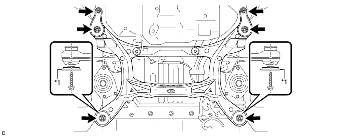
Text in Illustration *1 Rear Lower Suspension Brace - - - Torque:
- Bolt
- 158 N*m { 1612 kgf*cm, 117 ft.*lbf }
- Nut
- 32 N*m { 327 kgf*cm, 24 ft.*lbf }
Note
Be sure to install the rear suspension member with the rear lower suspension braces facing in the correct direction as shown in the illustration.
-
Lower the jack.
-
Connect the rear upper control arm assembly LH.
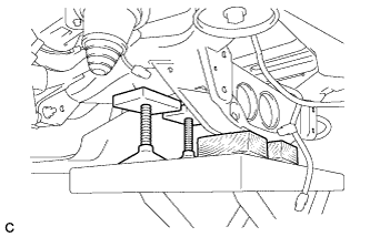
-
Using a brass bar and a hammer, push out the bushing until it is positioned as shown in the illustration.
Tech Tips
Pushing out the bushing makes it easier to connect the rear upper control arm assembly LH.
-
Text in Illustration *1 Jack *2 Wooden Block Using a jack and wooden block, jack up the rear axle assembly LH to replicate standard vehicle height conditions.
-
Connect the rear upper control arm assembly LH to the rear axle carrier sub-assembly LH with the bolt and nut.
- Torque:
- 145 N*m { 1479 kgf*cm, 107 ft.*lbf }
Note
-
Insert the bolt with the threaded end facing the rear side of the vehicle.
-
Since the stopper nut is used, tighten the bolt.
-
Slowly lower the rear axle assembly LH.
-
-
Connect the rear upper control arm assembly RH.
Tech Tips
Perform the same procedure as the LH side.
-
-
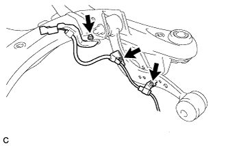
INSTALL FRAME WIRE
-
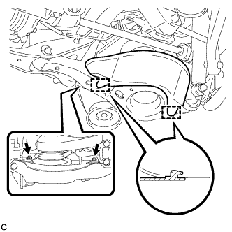
Install the bolt and engage the 4 clamps, and then connect the 3 connectors to install the frame wire to the rear suspension member as shown in the illustration.
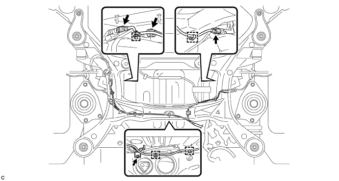
- Torque:
- 5.0 N*m { 51 kgf*cm, 44 in.*lbf }
Note
Do not twist the frame wire when installing it.
-
-
TEMPORARILY TIGHTEN REAR NO. 2 SUSPENSION ARM ASSEMBLY LH
-
Temporarily tighten the rear No. 2 suspension arm assembly to the rear suspension member with the rear suspension toe adjust cam sub-assembly, No. 2 camber adjust cam and nut.
Note
-
Insert the rear suspension toe adjust cam sub-assembly with the threaded end facing the front side of the vehicle.
-
When tightening the nut, keep the toe adjust cam from rotating.
-
Fully tighten the nut after stabilizing the suspension.
-
-
Text in Illustration *1 Jack *2 Wooden Block Support the rear No. 2 suspension arm assembly with a jack using a wooden block as shown in the illustration.
-
Install the rear lower coil spring insulator to the rear No. 2 suspension arm assembly.
-
Text in Illustration *1 Identification Mark Set the rear coil spring to the rear No. 2 suspension arm assembly.
Note
Set the rear coil spring so that the identification mark is positioned as shown in the illustration.
-
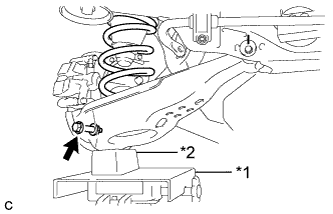
Text in Illustration *1 Jack *2 Wooden Block Using a jack and wooden block, slowly jack up the rear No. 2 suspension arm assembly.
-
Install the rear No. 2 suspension arm assembly and rear coil spring with the bolt and nut.
- Torque:
- 100 N*m { 1020 kgf*cm, 74 ft.*lbf }
Note
-
Insert the bolt with the threaded end facing the front side of the vehicle.
-
Since the stopper nut is used, tighten the bolt.
-
-
TEMPORARILY TIGHTEN REAR NO. 2 SUSPENSION ARM ASSEMBLY RH
Tech Tips
Perform the same procedure as the LH side.
-
INSTALL REAR STABILIZER BAR
-
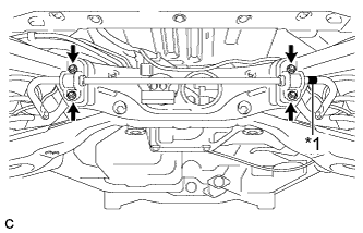
Text in Illustration *1 Identification Mark Install the rear stabilizer bar with 2 rear stabilizer bushings and 2 rear No. 1 stabilizer bar brackets with the 4 nuts.
- Torque:
- 75 N*m { 765 kgf*cm, 55 ft.*lbf }
Note
Ensure that the identification mark faces the right side of the vehicle.
-
-
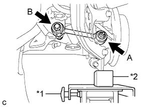
INSTALL REAR STABILIZER LINK SUB-ASSEMBLY LH
-
Install the rear stabilizer link sub-assembly to the rear stabilizer bar with the nut (B).
- Torque:
- 90 N*m { 918 kgf*cm, 66 ft.*lbf }
Tech Tips
If the ball joint turns together with the nut (B), use a hexagon wrench (6 mm) to hold the stud bolt.
-
Install the rear stabilizer link sub-assembly to the rear No. 2 suspension arm assembly with the 2 nuts (A).
- Torque:
- 82 N*m { 836 kgf*cm, 60 ft.*lbf }
-
-
INSTALL REAR STABILIZER LINK SUB-ASSEMBLY RH
Tech Tips
Perform the same procedure as the LH side.
-
INSTALL REAR SPEED SENSOR WIRE LH
-
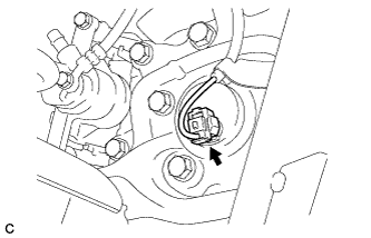
Connect the connector to the rear speed sensor.
-
Install the No. 1 bracket with the bolt.
- Torque:
- 8.0 N*m { 82 kgf*cm, 71 in.*lbf }
-
-
INSTALL REAR SPEED SENSOR WIRE RH
Tech Tips
Perform the same procedure as the LH side.
-
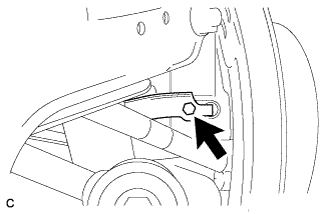
INSTALL REAR FLEXIBLE HOSE LH
-
Install the rear flexible hose LH to the rear upper control arm assembly LH with the bolt.
- Torque:
- 19 N*m { 192 kgf*cm, 14 ft.*lbf }
Note
-
Do not twist the rear flexible hose when connecting it.
-
Do not damage the rear flexible hose when reassembling it.
-
If the rear flexible hose is damaged, replace it with a new one.
-
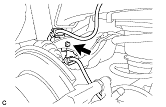
Install the rear flexible hose LH to the bracket with a new clip.
Note
-
Install the clip as far as it will go.
-
Do not twist the rear flexible hose when installing it.
-
-
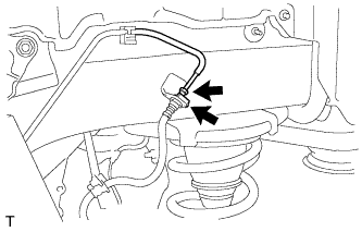
Using a union nut wrench, connect the brake line to the rear flexible hose LH.
- Torque:
- 15 N*m { 155 kgf*cm, 11 ft.*lbf }
Note
-
Do not bend or damage the brake line.
-
Do not allow any foreign matter such as dirt and dust to enter the brake line.
-
Use the formula to calculate special torque values for situations where the union nut wrench is combined with a torque wrench Click here.
-
-
INSTALL REAR FLEXIBLE HOSE RH
Tech Tips
Perform the same procedure as the LH side.
-
INSTALL TAIL EXHAUST PIPE ASSEMBLY
-
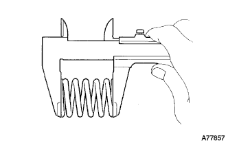
Using a vernier caliper, measure the free length of the compression springs.
Minimum 41.5 mm (1.64 in.) Tech Tips
If the free length is less than minimum, replace the compression spring.
-
Fully insert a new gasket to the center exhaust pipe assembly.
-
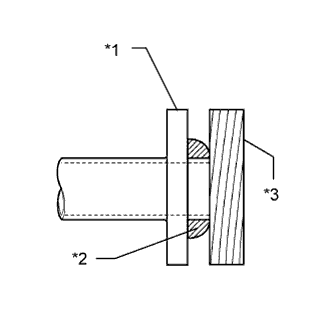
Text in Illustration *1 Center Exhaust Pipe Assembly *2 Gasket *3 Wooden Block Using a plastic hammer and wooden block, tap in the new gasket until its surface is flush with the center exhaust pipe assembly.
Note
-
Be careful with the installation direction of the gasket.
-
Do not reuse the gasket.
-
Do not damage the gasket.
-
Do not push in the gasket by using the exhaust pipe when connecting it.
-
-
Connect the tail exhaust pipe assembly to the 4 exhaust pipe supports.
-
Install the tail exhaust pipe assembly with the 2 bolts and 2 compression springs.
- Torque:
- 43 N*m { 440 kgf*cm, 32 ft.*lbf }
-
-
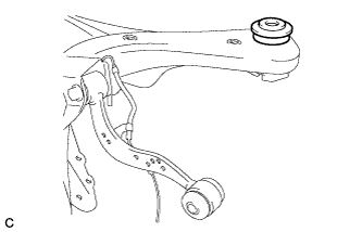
STABILIZE SUSPENSION
-
Text in Illustration *1 Jack *2 Wooden Block Jack up the rear No. 2 suspension arm assembly, placing a wooden block underneath to avoid damage. Apply load to the suspension so that the rear upper control arm assembly is positioned as shown in the illustration.
Standard Length (A) 24.3 mm (0.957 in.) CAUTION:
Do not jack up the rear No. 2 suspension arm assembly too high as the vehicle may fall.
Tech Tips
-
If the rear upper control arm assembly cannot be positioned as shown in the illustration even when the rear No. 2 suspension arm assembly is jacked up, apply additional load such as by placing a weight in the luggage compartment.
-
Use the same procedure for the RH side and LH side.
-
-
-
FULLY TIGHTEN REAR NO. 1 SUSPENSION ARM ASSEMBLY LH
-
Using a ball joint lock nut wrench, fully tighten the bolt (B).
- Torque:
- 150 N*m { 1530 kgf*cm, 111 ft.*lbf }
Note
-
The final torque must be applied under standard vehicle height conditions.
-
Since the stopper nut is used, tighten the bolt (B).
-
Use the formula to calculate special torque values for situations where the ball joint lock nut wrench is combined with a torque wrench Click here.
-
Fully tighten the nut (A).
- Torque:
- 150 N*m { 1530 kgf*cm, 111 ft.*lbf }
Note
The final torque must be applied under standard vehicle height conditions.
-
-
FULLY TIGHTEN REAR NO. 1 SUSPENSION ARM ASSEMBLY RH
Tech Tips
Perform the same procedure as the LH side.
-
FULLY TIGHTEN REAR NO. 2 SUSPENSION ARM ASSEMBLY LH
-
Text in Illustration *1 Matchmark Align the matchmarks on the adjust cams and rear suspension member sub-assembly.
-
Fully tighten the nut.
- Torque:
- 100 N*m { 1020 kgf*cm, 74 ft.*lbf }
Note
-
The final torque must be applied under standard vehicle height conditions.
-
When tightening the nut, keep the toe adjust cam from rotating.
-
-
FULLY TIGHTEN REAR NO. 2 SUSPENSION ARM ASSEMBLY RH
Tech Tips
Perform the same procedure as the LH side.
-
INSTALL REAR SUSPENSION ARM COVER LH
-
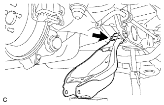
Install the rear suspension arm cover to the rear No. 2 suspension arm assembly with the 2 bolts as shown in the illustration.
- Torque:
- 12 N*m { 122 kgf*cm, 9 ft.*lbf }
-
-
INSTALL REAR SUSPENSION ARM COVER RH
Tech Tips
Perform the same procedure as the LH side.
-
BLEED BRAKE SYSTEM
-
INSTALL REAR WHEELS
- Torque:
- 103 N*m { 1050 kgf*cm, 76 ft.*lbf }
-
INSPECT FOR EXHAUST GAS LEAK
-
INSPECT AND ADJUST REAR WHEEL ALIGNMENT
-
CHECK FOR SPEED SENSOR SIGNAL
-
HEIGHT CONTROL SENSOR SIGNAL INITIALIZATION
-
INSPECT AND ADJUST HEADLIGHT AIMING