REAR SUSPENSION MEMBER (for 2WD) REMOVAL

-
REMOVE REAR WHEELS
-
DRAIN BRAKE FLUID
-
REMOVE TAIL EXHAUST PIPE ASSEMBLY
-
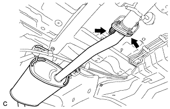
Remove the 2 bolts and 2 compression springs.
-
Remove the tail exhaust pipe assembly from the 4 exhaust pipe supports.
-
Remove the gasket from the center exhaust pipe assembly.
-
-
SEPARATE REAR FLEXIBLE HOSE LH
-
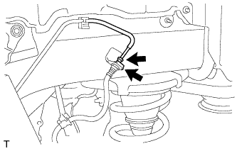
Using a union nut wrench, disconnect the brake line from the rear flexible hose LH.
Note
-
Do not bend or damage the brake line.
-
Do not allow any foreign matter such as dirt and dust to enter the brake line.
-
-
Remove the clip and separate the rear flexible hose LH.
-
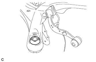
Remove the bolt and separate the rear flexible hose LH from the rear upper control arm assembly LH.
-
-
SEPARATE REAR FLEXIBLE HOSE RH
Tech Tips
Perform the same procedure as the LH side.
-
REMOVE REAR SUSPENSION ARM COVER LH
-
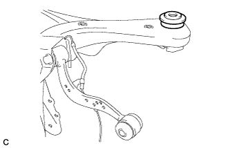
Remove the 2 bolts and rear suspension arm cover from the rear No. 2 suspension arm assembly.
-
-
REMOVE REAR SUSPENSION ARM COVER RH
Tech Tips
Perform the same procedure as the LH side.
-
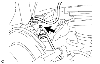
SEPARATE REAR SPEED SENSOR WIRE LH
-
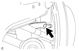
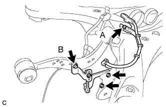
Remove the bolt and No. 1 bracket.
-
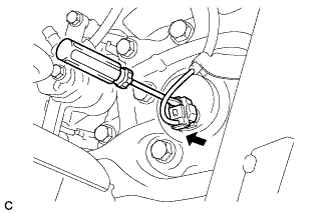
Using a screwdriver, disconnect the connector from the rear speed sensor.
Note
Be careful not to damage the rear speed sensor.
-
-
SEPARATE REAR SPEED SENSOR WIRE RH
Tech Tips
Perform the same procedure as the LH side.
-
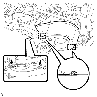
REMOVE REAR STABILIZER LINK SUB-ASSEMBLY LH
-
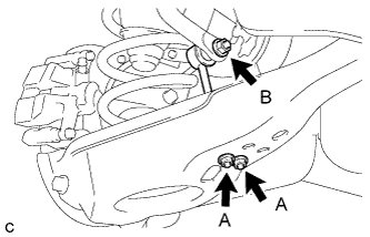
Remove the 2 nuts (A) and rear stabilizer link sub-assembly from the rear No. 2 suspension arm assembly.
-
Remove the nut (B) and separate the rear stabilizer link sub-assembly from the rear stabilizer bar.
Tech Tips
If the ball joint turns together with the nut (B), use a hexagon wrench (6 mm) to hold the stud bolt.
-
-
REMOVE REAR STABILIZER LINK SUB-ASSEMBLY RH
Tech Tips
Perform the same procedure as the LH side.
-
REMOVE REAR STABILIZER BAR
-
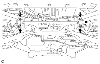
Remove the 4 nuts and rear stabilizer bar with 2 rear stabilizer bushings and 2 rear No. 1 stabilizer bar brackets.
-
-
REMOVE REAR NO. 2 SUSPENSION ARM ASSEMBLY LH
-
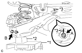
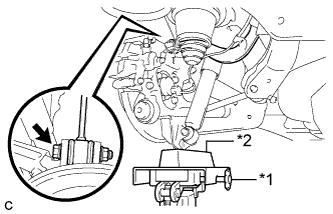
Text in Illustration *1 Jack *2 Wooden Block *3 Matchmark Put matchmarks on the adjust cams and the rear suspension member sub-assembly.
-
Using a jack and wooden block, jack up the rear No. 2 suspension arm assembly to replicate standard vehicle height conditions.
CAUTION:
Do not jack up the rear No. 2 suspension arm assembly too high as the vehicle may fall.
-
Loosen the nut (A).
Note
When loosening the nut (A), keep the toe adjust cam from rotating.
-
Remove the bolt (B) and nut, and separate the rear No. 2 suspension arm assembly from the rear axle carrier sub-assembly.
Note
Since the stopper nut is used, loosen the bolt (B).
-
Slowly lower the rear No. 2 suspension arm assembly, and remove the rear coil spring.
-
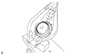
Remove the rear lower coil spring insulator from the rear No. 2 suspension arm assembly.
-
Remove the nut, No. 2 camber adjust cam, rear suspension toe adjust cam sub-assembly and rear No. 2 suspension arm assembly.
Note
When removing the nut, keep the toe adjust cam from rotating.
-
-
REMOVE REAR NO. 2 SUSPENSION ARM ASSEMBLY RH
Tech Tips
Perform the same procedure as the LH side.
-
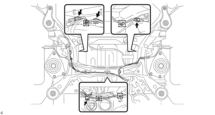
SEPARATE FRAME WIRE
-
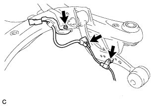
Remove the bolt and disconnect the 3 connectors, and then disengage the 4 clamps to separate the frame wire from rear suspension member as shown in the illustration.
-
-
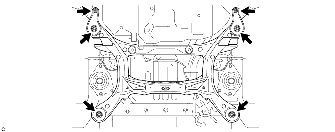
REMOVE REAR SUSPENSION MEMBER SUB-ASSEMBLY
-
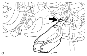
Separate the rear upper control arm assembly LH.
-
Text in Illustration *1 Jack *2 Wooden Block Using a jack and wooden block, jack up the rear axle assembly LH to replicate standard vehicle height conditions.
-
Remove the bolt and nut, and then separate the rear upper control arm assembly LH from the rear axle carrier sub-assembly LH.
Note
Since the stopper nut is used, loosen the bolt.
-
Slowly lower the rear axle assembly LH.
-
-
Separate the rear upper control arm assembly RH.
Tech Tips
Perform the same procedure as the LH side.
-
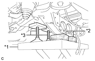
Text in Illustration *1 Jack *2 Wooden Block *3 Attachment Support the rear suspension member with a jack using 2 wooden blocks and 2 attachments or equivalent tools as shown in the illustration.
Note
Make sure to secure the rear suspension member to prevent it from dropping.
-
Remove the 2 nuts, 4 bolts, 2 rear lower suspension braces and 2 rear lower suspension member stoppers.
-
Remove the rear No. 1 suspension arm assembly LH.
-
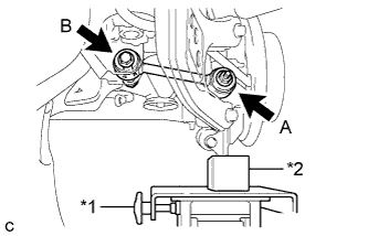
Text in Illustration *1 Jack *2 Wooden Block Using a jack and wooden block, jack up the rear axle assembly LH to replicate standard vehicle height conditions.
-
Remove the nut (A) and the spacer.
-
Remove the bolt (B), nut and rear No. 1 suspension arm assembly LH.
Note
Since the stopper nut is used, loosen the bolt (B).
-
Slowly lower the rear axle assembly LH.
-
-
Remove the rear No. 1 suspension arm assembly RH.
Tech Tips
Perform the same procedure as the LH side.
-
Slowly lower the rear suspension member.
Note
When lowering the rear suspension member, be careful not to damage the vehicle body or other components installed on the vehicle.
-
-
REMOVE REAR SUSPENSION MEMBER UPPER STOPPER
-
Remove the 2 rear suspension member upper stoppers.
-
-
REMOVE REAR SUSPENSION MEMBER REAR UPPER STOPPER
-
Remove the 2 rear suspension member rear upper stoppers.
-
-
REMOVE REAR HEIGHT CONTROL SENSOR SUB-ASSEMBLY RH (w/ HID Headlight System)
-
Remove the bolt (B) and separate the rear height control sensor sub-assembly RH from the rear upper control arm assembly RH.
-
Remove the bolt (A), 2 nuts and rear height control sensor sub-assembly RH from the rear suspension member sub-assembly.
-
-
REMOVE REAR SPEED SENSOR WIRE LH
-
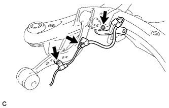
Remove the 2 bolts, nut and rear speed sensor wire LH.
-
-
REMOVE REAR SPEED SENSOR WIRE RH
-
Remove the 2 bolts, nut and rear speed sensor wire RH.
-
-
REMOVE REAR UPPER CONTROL ARM ASSEMBLY LH
-
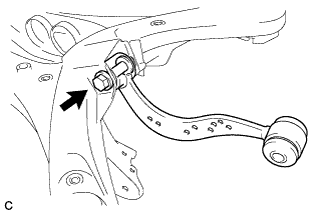
Remove the bolt, nut and rear upper control arm assembly LH from the rear suspension member sub-assembly.
Note
Since the stopper nut is used, loosen the bolt.
-
-
REMOVE REAR UPPER CONTROL ARM ASSEMBLY RH
Tech Tips
Perform the same procedure as the LH side.
-
REMOVE REAR SUSPENSION MEMBER FRONT BODY MOUNTING CUSHION (for LH Side)
-
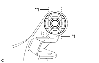
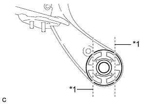
Text in Illustration *1 Bend Portion Using a chisel and hammer, bend the 2 portions of the rear suspension member front body mounting cushion rib.
Note
Make sure to bend the 2 portions of the cushion rib until the claws of SST can fit securely.
-
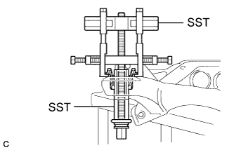
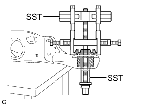
Install SST as shown in the illustration.
- SST
- 09830-10010 ( 09830-01010, 09830-01040, 09830-01050 )
- 09950-40011 ( 09951-04020, 09952-04010, 09954-04010, 09955-04051, 09958-04011 )
Note
Apply a small amount of grease to the threads and tip of SST (center bolt) before use.
-
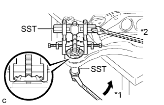
Text in Illustration *1 Turn *2 Hold Using SST, separate the rear suspension member front body mounting cushion (LH Side) from the rear suspension member sub-assembly, while applying grease to the clearance between the rear suspension member front body mounting cushion (LH Side) and the rear suspension member sub-assembly.
- SST
- 09830-10010 ( 09830-01010, 09830-01040, 09830-01050 )
- 09950-40011 ( 09951-04020, 09952-04010, 09954-04010, 09955-04051, 09958-04011 )
Note
-
Set the claws of SST onto the rear suspension member sub-assembly securely as shown in the illustration.
-
Be careful as the rear suspension member front body mounting cushion may fly out.
-
The rear suspension member front body mounting cushion cannot be reused.
-
Remove SST and the rear suspension member front body mounting cushion (LH Side) from the rear suspension member sub-assembly.
-
-
REMOVE REAR SUSPENSION MEMBER FRONT BODY MOUNTING CUSHION (for RH Side)
Tech Tips
Perform the same procedure as the LH side.
-
REMOVE REAR SUSPENSION MEMBER REAR BODY MOUNT CUSHION LH
-
Text in Illustration *1 Bend Portion Using a chisel and hammer, bend the 2 portions of the rear suspension member rear body mounting cushion LH rib.
Note
Make sure to bend the 2 portions of the cushion rib until the claws of SST can fit securely.
-
Install SST as shown in the illustration.
- SST
- 09830-10010 ( 09830-01010, 09830-01040, 09830-01050 )
- 09950-40011 ( 09951-04020, 09952-04010, 09954-04010, 09955-04051, 09958-04011 )
Note
Apply a small amount of grease to the threads and tip of SST (center bolt) before use.
-
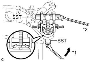
Text in Illustration *1 Turn *2 Hold Using SST, separate the rear suspension member rear body mounting cushion LH from the rear suspension member sub-assembly, while applying grease to the clearance between the rear suspension member rear body mounting cushion LH and the rear suspension member sub-assembly.
- SST
- 09830-10010 ( 09830-01010, 09830-01040, 09830-01050 )
- 09950-40011 ( 09951-04020, 09952-04010, 09954-04010, 09955-04051, 09958-04011 )
Note
-
Set the claws of SST onto the rear suspension member sub-assembly securely as shown in the illustration.
-
Be careful as the rear suspension member rear body mounting cushion may fly out.
-
The rear suspension member rear body mounting cushion cannot be reused.
-
Remove SST and the rear suspension member rear body mounting cushion LH from the rear suspension member sub-assembly.
-
-
REMOVE REAR SUSPENSION MEMBER REAR BODY MOUNT CUSHION RH
Tech Tips
Perform the same procedure as the LH side.
-
REMOVE HOLE PLUG
-
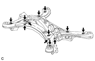
Remove the 12 hole plugs from the rear suspension member as shown in the illustration.
-