REAR DIFFERENTIAL CARRIER ASSEMBLY INSTALLATION

Note
If installing a new rear differential carrier assembly, remove the 2 differential side seal caps before installing the rear drive shaft assembly.
-
TEMPORARILY TIGHTEN NO. 1 REAR DIFFERENTIAL SUPPORT
-
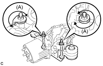
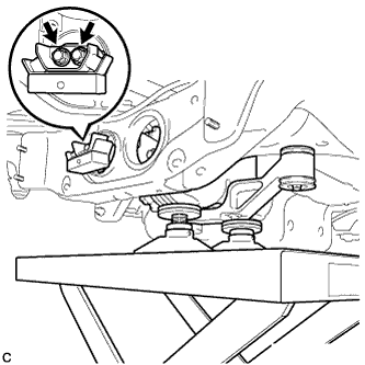
Temporarily install the No. 1 rear differential support to the rear differential carrier assembly with 2 new bolts and 2 new nuts.
Note
-
Be sure to install the No. 1 rear differential support facing the direction shown in the illustration.
-
Be sure to install each nut tabs to position (A) shown in the illustration.
Tech Tips
The nuts have tabs to prevent them from rotating.
-
-
-
INSTALL UPPER REAR DIFFERENTIAL MOUNT STOPPER
-
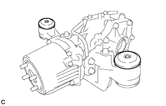
Install the 2 upper rear differential mount stoppers to the No. 1 rear differential support as shown in the illustration.
-
-
INSTALL DIFFERENTIAL SUPPORT
-
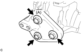
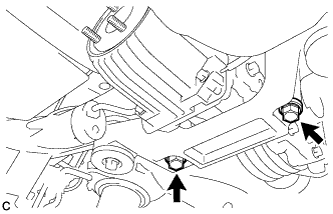
Install the differential support to the rear differential carrier assembly with 3 new bolts.
- Torque:
- 167 N*m { 1700 kgf*cm, 123 ft.*lbf }
Note
Tighten the bolt (A) first shown in the illustration.
-
-
TEMPORARILY TIGHTEN REAR DIFFERENTIAL CARRIER ASSEMBLY WITH DIFFERENTIAL SUPPORT
-
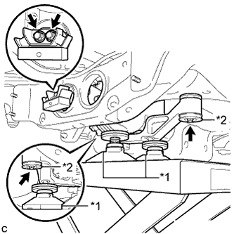
Text in Illustration *1 Attachment *2 Lower Rear Differential Mount Stopper Support the rear differential carrier assembly with differential support with a jack using 3 attachments as shown in the illustration.
-
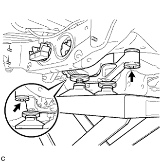
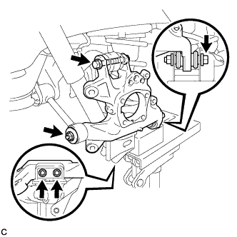
Jack up the rear differential carrier assembly with differential support, temporarily install the rear differential carrier assembly with differential support to the front side of the rear suspension member assembly with the 2 lower rear differential mount stoppers, 2 new bolts and 2 new nuts.
Note
Be sure to install the lower rear differential mount stoppers with the convex side facing upward.
Tech Tips
The nuts have tabs to prevent them from rotating.
-
Temporarily install the rear differential carrier assembly with differential support and rear differential dynamic damper to the rear side of the rear suspension member assembly with the 2 new rear mounting bolts.
-
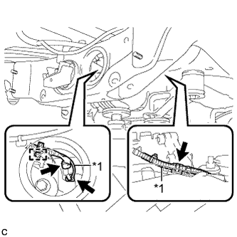
Text in Illustration *1 Vacuum Hose Connect the vacuum hose to the 2 clamps, connect the connector, and install the clamp to the connector bracket.
-
-
FULLY TIGHTEN REAR DIFFERENTIAL CARRIER ASSEMBLY WITH DIFFERENTIAL SUPPORT
Note
Do not tighten the bolts with the inner cylinder or rear differential mount cushion tilted.
-
Install the rear differential carrier assembly with differential support and rear differential dynamic damper to the rear side of the rear suspension member assembly with the 2 new rear mounting bolts.
- Torque:
- 95 N*m { 970 kgf*cm, 70 ft.*lbf }
-
Tighten the 2 new bolts.
- Torque:
- 86 N*m { 877 kgf*cm, 63 ft.*lbf }
Tech Tips
-
Tighten the bolts only if the No. 1 rear differential support has been removed from the rear differential carrier assembly.
-
Lower the jack to the extent that the bolts can still be tightened.
-
Tighten the rear differential carrier assembly with differential support to the front side of the rear suspension member assembly with the 2 new bolts.
- Torque:
- 80 N*m { 816 kgf*cm, 59 ft.*lbf }
-
Lower the jack.
-
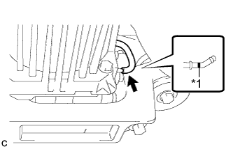
Text in Illustration *1 Paint Mark Connect the vacuum hose to the electro magnetic control coupling sub-assembly.
Note
Connect the vacuum hose until it reaches the paint mark.
-
-
INSTALL STABILIZER LINK SUB-ASSEMBLY (for LH Side)
-
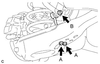
Install the rear stabilizer link sub-assembly to the rear stabilizer bar with the nut (B).
- Torque:
- 90 N*m { 918 kgf*cm, 66 ft.*lbf }
Tech Tips
If the ball joint turns together with the nut (B), use a hexagon wrench (6 mm) to hold the stud bolt.
-
Install the rear stabilizer link sub-assembly to the rear No. 2 suspension arm assembly with the 2 nuts (A).
- Torque:
- 82 N*m { 836 kgf*cm, 60 ft.*lbf }
-
-
INSTALL STABILIZER LINK SUB-ASSEMBLY (for RH Side)
Tech Tips
Perform the same procedure as the LH side.
-
INSTALL REAR STABILIZER BAR
-
Type A:
-
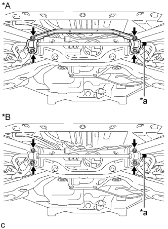
Text in Illustration *A Type A *B Type B *a Identification mark Install the rear stabilizer bar with 2 rear stabilizer bushings and rear No. 1 stabilizer bar bracket with the 4 nuts.
- Torque:
- 75 N*m { 765 kgf*cm, 55 ft.*lbf }
Note
Ensure that the identification mark faces the right side of the vehicle.
-
-
Type B:
-
Install the rear stabilizer bar with 2 rear stabilizer bushings and 2 rear No. 1 stabilizer bar brackets with the 4 nuts.
- Torque:
- 75 N*m { 765 kgf*cm, 55 ft.*lbf }
Note
Ensure that the identification mark faces the right side of the vehicle.
-
-
-
INSTALL TAIL EXHAUST PIPE ASSEMBLY
-
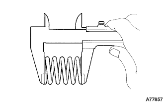
Using a vernier caliper, measure the free length of the compression springs.
Minimum length 38.5 mm (1.52 in.) If the free length is less than the minimum, replace the compression spring.
-
Fully insert a new gasket to the center exhaust pipe assembly.
-
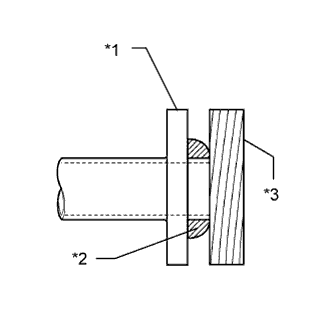
Text in Illustration *1 Center Exhaust Pipe Assembly *2 Gasket *3 Wooden Block Using a plastic hammer and wooden block, tap in the new gasket until its surface is flush with the center exhaust pipe assembly.
Note
-
Be sure to install the gasket in the correct direction.
-
Do not reuse the gasket.
-
Do not damage the gasket.
-
Do not push in the gasket by using the exhaust pipe when connecting it.
-
-
Connect the tail exhaust pipe assembly to the 4 exhaust pipe supports.
-
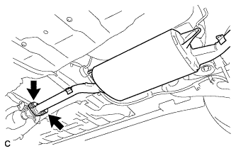
Install the tail exhaust pipe assembly with the 2 bolts and 2 compression springs.
- Torque:
- 43 N*m { 440 kgf*cm, 32 ft.*lbf }
-
-
INSTALL PROPELLER WITH CENTER BEARING SHAFT ASSEMBLY
Tech Tips
Refer to the procedure from Install Propeller with Center Bearing Shaft Assembly Click here.
-
REMOVE REAR AXLE CARRIER SUB-ASSEMBLY LH
-
Using a jack and wooden block, jack up the rear No. 2 suspension arm assembly LH to replicate standard vehicle height conditions.
CAUTION:
Do not jack up the rear No. 2 suspension arm assembly LH too high as the vehicle may fall.
-
Remove the 4 bolts, 3 nuts and spacer to remove the rear axle carrier sub-assembly LH from the rear No. 1 suspension arm assembly LH, rear No. 2 suspension arm assembly LH, rear upper control arm assembly LH and rear lower shock absorber bracket sub-assembly LH.
-
-
INSTALL REAR DRIVE SHAFT SNAP RING LH
-
Install a new rear drive shaft snap ring.
-
-
INSTALL REAR DRIVE SHAFT ASSEMBLY LH
-
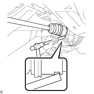
Align the shaft splines and install the rear drive shaft assembly with a brass bar and a hammer.
Note
-
Set the snap ring with the opening facing downward.
-
Be careful not to damage the oil seal, boot or dust cover.
-
Install the rear drive shaft assembly while keeping it level.
-
-
-
REMOVE REAR AXLE CARRIER SUB-ASSEMBLY RH
Tech Tips
Perform the same procedure as the LH side.
-
INSTALL REAR DRIVE SHAFT SNAP RING RH
Tech Tips
Perform the same procedure as the LH side.
-
INSTALL REAR DRIVE SHAFT ASSEMBLY RH
Tech Tips
Perform the same procedure as the LH side.
-
ADD DIFFERENTIAL OIL
-
When reusing the rear differential carrier assembly:
-
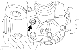
Using a hexagon wrench (10 mm), install a new gasket with the rear differential drain plug.
- Torque:
- 39 N*m { 398 kgf*cm, 29 ft.*lbf }
-
Add differential oil Click here.
-
-
When using a new rear differential carrier assembly:
-
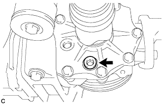
Using a hexagon wrench (10 mm), remove the differential inspection plug and gasket.
-
Add differential oil Click here.
-
-
-
INSPECT DIFFERENTIAL OIL
-
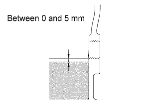
Check that the oil level is between 0 and 5 mm (0 and 0.197 in.) from the bottom lip of the differential inspection plug opening.
-
Inspect for oil leak if the oil level is low.
-
-
INSTALL DIFFERENTIAL INSPECTION PLUG
-
Using a hexagon wrench (10 mm), install the differential inspection plug and a new gasket.
- Torque:
- 39 N*m { 398 kgf*cm, 29 ft.*lbf }
-
-
INSPECT FOR DIFFERENTIAL OIL LEAK
-
INSTALL REAR AXLE CARRIER SUB-ASSEMBLY LH
Tech Tips
Refer to the procedure from Temporarily Tighten Rear Axle Carrier Sub-assembly Click here.
-
INSTALL REAR AXLE CARRIER SUB-ASSEMBLY RH
Tech Tips
Perform the same procedure as the LH side.
-
INSPECT FOR EXHAUST GAS LEAK