REAR DIFFERENTIAL CARRIER OIL SEAL REPLACEMENT

-
REMOVE NO. 1 REAR DIFFERENTIAL SUPPORT
-
SEPARATE ELECTRO MAGNETIC CONTROL COUPLING WIRE HARNESS
-
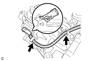
Disengage the claw and separate the electro magnetic control coupling wire harness form the 2 clamps.
-
-
REMOVE CONNECTOR BRACKET
-
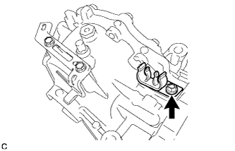
Remove the bolt and connector bracket.
-
Remove the clamp from the connector bracket.
-
-
REMOVE ELECTRO MAGNETIC CONTROL COUPLING SUB-ASSEMBLY
-
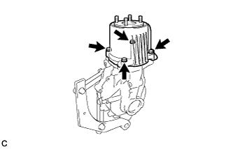
Remove the 4 bolts.
-
Using a plastic hammer, lightly tap the electro magnetic control coupling sub-assembly to remove it from the rear differential carrier assembly.
-
-
REMOVE CONICAL WASHER
-
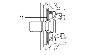
Text in Illustration *1 Conical Washer Remove the conical washer from the rear differential carrier assembly.
-
-
REMOVE SPACER
-
Text in Illustration *1 Spacer Remove the spacer from the rear differential carrier assembly.
-
-
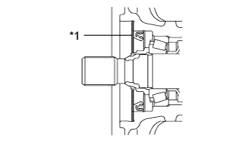
REMOVE DIAPHRAGM OIL SEAL
-
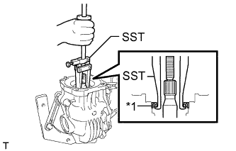
Text in Illustration *1 Diaphragm Oil Seal Using SST, remove the diaphragm oil seal from the rear differential carrier assembly.
- SST
- 09308-00010
-
-
INSTALL DIAPHRAGM OIL SEAL
-
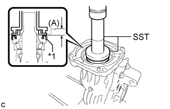
Text in Illustration *1 Diaphragm Oil Seal Using SST and a press, install a new diaphragm oil seal into the rear differential carrier assembly.
- SST
- 09506-35010
- 09554-22010
Note
-
Install the diaphragm oil seal uniformly.
-
Press fit the diaphragm oil seal straight.
Distance (A) 0.7 to 1.3 mm (0.0276 to 0.0512 in.) -
Apply a light coat of MP grease to the lip of the new diaphragm oil seal.
-
-
INSTALL SPACER
-
Text in Illustration *1 Spacer Install the spacer to the rear differential carrier assembly.
Note
Keep the spacer free of oil and foreign matter.
-
-
INSTALL CONICAL WASHER
-
Text in Illustration *1 Conical Washer Install the conical washer to the rear differential carrier assembly.
Note
-
Be sure to install the conical washer with the convex side facing the rear of the vehicle.
-
Keep the conical washer free of oil and foreign matter.
-
-
-
INSTALL ELECTRO MAGNETIC CONTROL COUPLING SUB-ASSEMBLY
-
Using a scraper and wire brush, remove the seal packing from the rear differential carrier assembly and electro magnetic control coupling sub-assembly.
Note
-
Do not damage the installation surface.
-
Be sure to completely remove all seal packing from the rear differential carrier assembly and electro magnetic control coupling sub-assembly.
-
Do not allow the removed seal packing to enter the rear differential carrier assembly and electro magnetic control coupling sub-assembly.
-
-
Using a non-residue solvent, remove grease and oil from the contact surfaces of the rear differential carrier assembly and the electro magnetic control coupling sub-assembly.
Note
Do not damage the installation surface.
-
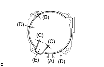
Apply seal packing to the areas indicated in the illustration of the rear differential carrier assembly.
Seal packing Toyota Genuine Seal Packing 1281, Three Bond 1281 or equivalent Note
-
Start applying seal packing within range (A).
-
Make sure that the clearance from the center of the bead is within 1 mm (0.0394 in.).
-
Apply seal packing in a continuous bead 2 to 3 mm (0.0787 to 0.118 in.) in diameter.
-
If there is an area where seal packing is not applied in a continuous bead, be sure to apply seal packing by overlapping the ends of the bead at least 10 mm (0.394 in.).
-
Stop applying seal packing after allowing it to overlap with the beginning of the bead by at least 10 mm (0.394 in.) within range (A) in the illustration.
-
Install the electro magnetic control coupling sub-assembly within 10 minutes after applying seal packing. If the electro magnetic control coupling sub-assembly is not installed within 10 minutes after applying seal packing, completely remove and then reapply seal packing.
-
After installing the electro magnetic control coupling sub-assembly, do not immediately add oil or drive the vehicle for at least 1 hour.
Tech Tips
-
(A) : 20 mm (0.787 in.)
-
(B) : 1.0 mm (0.0394 in.)
-
(C) : 1.4 mm (0.0551 in.)
-
(D) : 3.0 mm (0.118 in.)
-
(E) : 2.0 mm (0.0787 in.)
The center of the bead
-
-
Install the electro magnetic control coupling sub-assembly with the 4 bolts.
- Torque:
- 20 N*m { 200 kgf*cm, 14 ft.*lbf }
Note
-
Do not damage the diaphragm oil seal.
-
Do not damage the contact surface of the rear differential carrier assembly and electro magnetic control coupling sub-assembly.
-
-
INSTALL CONNECTOR BRACKET
-
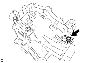
Install the connector bracket to the rear differential carrier with the bolt.
- Torque:
- 20 N*m { 200 kgf*cm, 14 ft.*lbf }
-
-
INSTALL ELECTRO MAGNETIC CONTROL COUPLING WIRE HARNESS
-
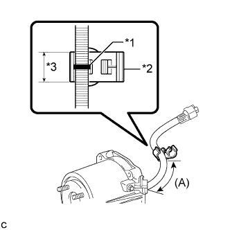
Text in Illustration *1 Identification Mark *2 Clamp *3 Width of Clamp Install a new clamp to the electro magnetic control coupling wire harness as shown in the illustration.
Note
Be sure to install the new clamp so that the identification mark is aligned with the clamp.
Distance (A) 83.5 to 89.5 mm (3.29 to 3.52 in.) -
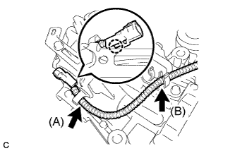
Engage the claw to install the electro magnetic control coupling wire harness connector.
-
Install the electro magnetic control coupling wire harness to the clamp (A).
-
Install the clamp (B) to the connector bracket.
Note
Do not damage the electro magnetic control coupling wire harness.
-
-
TEMPORARILY TIGHTEN NO. 1 REAR DIFFERENTIAL SUPPORT