-
Use the same procedure for the RH side and LH side.
-
The procedure listed below is for the LH side.
- Click here
DRAIN BRAKE FLUID
- Click here
REMOVE REAR WHEEL
- Click here
REMOVE REAR SUSPENSION ARM COVER
-
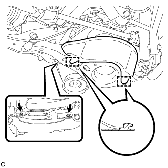
Remove the 2 bolts and rear suspension arm cover from the rear No. 2 suspension arm assembly.
-
- Click here
REMOVE REAR DISC BRAKE CALIPER ASSEMBLY
-
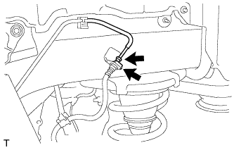
Using a union nut wrench, disconnect the brake line from the rear flexible hose.
Note:
-
Do not bend or damage the brake line.
-
Do not allow any foreign matter such as dirt and dust to enter the brake line.
-
-
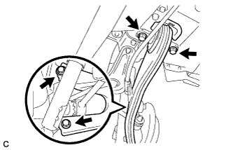
Remove the clip and separate the rear flexible hose.
-
Remove the bolt and separate the rear flexible hose from the rear upper control arm assembly.
-
Remove the 2 bolts and rear disc brake caliper assembly with rear flexible hose.
-
- Click here
REMOVE PARKING BRAKE SHOE ADJUSTING HOLE PLUG
-
Remove the parking brake shoe adjusting hole plug.
-
- Click here
REMOVE REAR DISC
-
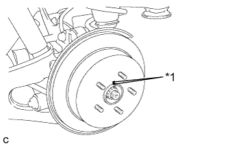
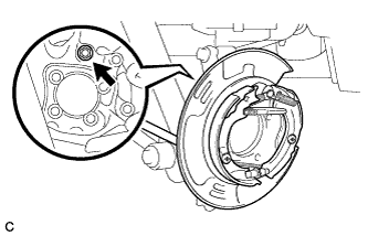
Put matchmarks on the rear disc and the axle hub.
Table 1. Text in Illustration *1 Matchmark -
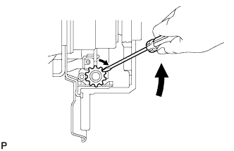
Release the parking brake and remove the rear disc.
Tip:If the disc can not be removed easily, use a screwdriver to turn the shoe adjuster as shown in the illustration in order to contract the parking brake shoes.
-
- Click here
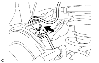
SEPARATE REAR SPEED SENSOR WIRE
-
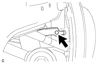
Remove the bolt and No. 1 bracket.
-
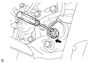
Using a screwdriver, disconnect the connector from the rear speed sensor.
Note:Be careful not to damage the rear speed sensor.
-
- Click here
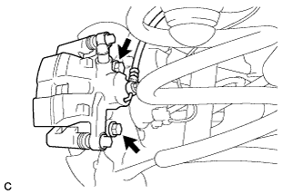
REMOVE REAR AXLE HUB AND BEARING ASSEMBLY
-
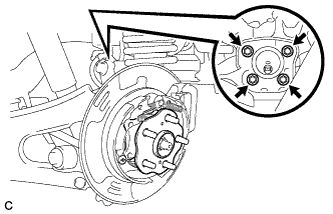
Remove the 4 bolts and the rear axle hub and bearing assembly from the rear axle carrier sub-assembly.
-
- Click here
LOOSEN PARKING BRAKE ASSEMBLY
-
Loosen the nut to separate the parking brake assembly after removing the rear trailing arm assembly.
-
- Click here
REMOVE REAR TRAILING ARM ASSEMBLY
-
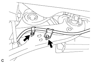
Remove the 2 bolts and separate the No. 3 parking brake cable assembly from the rear trailing arm assembly.
-
Using a jack and wooden block, jack up the rear No. 2 suspension arm assembly to replicate standard vehicle height conditions.
Table 2. Text in Illustration *1 Jack *2 Wooden Block CAUTION:Do not jack up the rear No. 2 suspension arm assembly too high as the vehicle may fall.
-
Remove the 4 bolts, 2 washers and rear trailing arm assembly.
-
Slowly lower the rear No. 2 suspension arm assembly.
-
- Click here
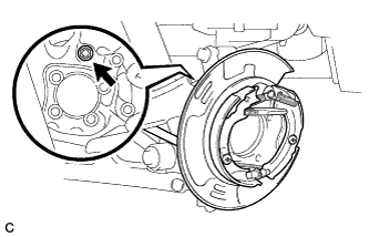
SEPARATE PARKING BRAKE ASSEMBLY
-
Remove the nut and separate the parking brake assembly from the rear axle carrier sub-assembly.
Note:Use wire or an equivalent tool to keep the parking brake assembly from hanging down by the parking brake cable.
-
- Click here
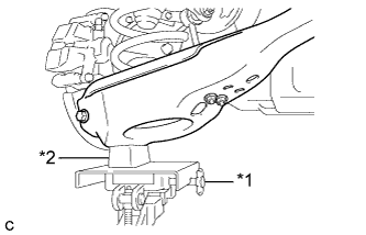
REMOVE REAR AXLE CARRIER SUB-ASSEMBLY
-
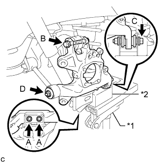
Using a jack and wooden block, jack up the rear No. 2 suspension arm assembly to replicate standard vehicle height conditions.
Table 3. Text in Illustration *1 Jack *2 Wooden Block CAUTION:Do not jack up the rear No. 2 suspension arm assembly too high as the vehicle may fall.
Note:Keep supporting the rear No. 2 suspension arm assembly until the installation of the rear axle carrier sub-assembly has been completed.
-
Remove the 2 bolts (A) to separate the rear axle carrier sub-assembly from the rear lower shock absorber bracket sub-assembly.
-
Remove the bolt (B) and nut, and then separate the rear upper control arm assembly from the rear axle carrier sub-assembly.
Note:Since the stopper nut is used, loosen the bolt (B).
-
Remove the bolt (C) and nut to separate the rear axle carrier sub-assembly from the rear No. 2 suspension arm assembly.
Note:Since the stopper nut is used, loosen the bolt (C).
-
Remove the nut (D), spacer and rear axle carrier sub-assembly from the rear No. 1 suspension arm assembly.
-