PROPELLER SHAFT ASSEMBLY INSTALLATION

-
TEMPORARILY TIGHTEN PROPELLER WITH CENTER BEARING SHAFT ASSEMBLY
-
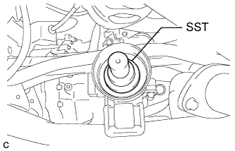
Remove SST from the transaxle.
-
Install the propeller with center bearing shaft assembly.
Note
-
Be careful not to damage the oil seal.
-
Be careful not to damage the universal joint boot when installing the propeller shaft.
-
-
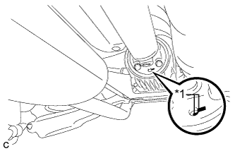
Text in Illustration *1 Matchmark Align the matchmarks on the rear propeller shaft and the electromagnetic control coupling assembly and install the 4 nuts and 4 No. 2 center support bearing washers.
Note
Do not allow grease to adhere to the bolts or washers.
-
Temporarily install the propeller with center bearing shaft assembly with the 4 bolts, and 4 No. 2 center support bearing washers.
Note
-
Reuse the No. 2 center support bearing washers.
-
Do not allow grease to adhere to the bolts or washers.
-
-
Fully tighten the 4 nuts.
- Torque:
- 74 N*m { 750 kgf*cm, 54 ft.*lbf }
-
-
FULLY TIGHTEN PROPELLER WITH CENTER BEARING SHAFT ASSEMBLY
-
Depress the brake pedal and hold it.
-
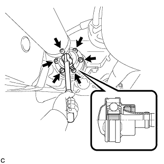
Remove the piece of cloth or equivalent from the universal joint.
-
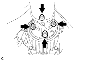
Using a hexagon wrench (6 mm), tighten the 6 bolts.
- Torque:
- 26 N*m { 265 kgf*cm, 19 ft.*lbf }
-
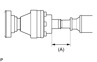
With the vehicle unloaded, adjust the dimension between the rear side of the cover and shaft as shown in the illustration.
Length (A) 65.5 to 70.5 mm (2.57 to 2.78 in.) -
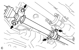
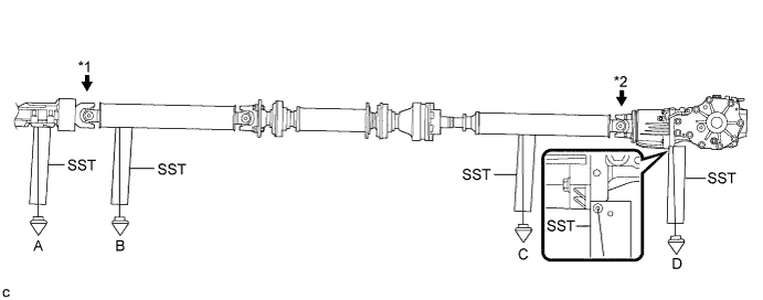
With the vehicle unloaded, adjust the front and rear dimensions between the edge surface of the center support bearing and the edge surface of the cushion respectively as shown in the illustration, and then tighten the bolts.

Text in Illustration *1 No. 2 Center Support Bearing Assembly (for Front Side) *2 No. 2 Center Support Bearing Assembly (for Rear Side) Length (A) 11.5 to 13.5 mm (0.453 to 0.532 in.) -
Fully tighten the 4 bolts.
- Torque:
- 74 N*m { 750 kgf*cm, 54 ft.*lbf }
-
Check that the center line of the bracket is at a right angle to the shaft axial direction.
-
-
INSPECT AND ADJUST TRANSFER OIL
-
Inspect and adjust transfer oil Click here.
-
-
INSPECT AND ADJUST JOINT ANGLE
-
If any vibration or noise occurs, perform joint angle check as follows and replace the No. 2 center support bearing washer with a proper one.
-
Turn the propeller shaft several times by hand to stabilize the center support bearings.
-
Using a jack, raise and lower the differential to stabilize the differential mounting cushion.
-
Remove the transfer dynamic damper.
Note
Measure the joint angle when the vehicle is raised using a four-post lift or when using a pit.
-
Using SST, measure the transfer installation angle (A) and front propeller shaft installation angle (B).
- SST
- 09370-50010
Text in Illustration *1 No. 1 Joint Angle *2 No. 4 Joint Angle No. 1 joint angle (A) - (B) = -3.02° to -1.02° -
Using SST, measure the rear propeller shaft installation angle (C) and rear differential shaft installation angle (D).
- SST
- 09370-50010
No. 4 joint angle (C) - (D) = 0.81° to 2.81° Tech Tips
If the calculated amount is not within the specification, adjust the joint angle with the No. 2 center support bearing washer.
Note
-
Make sure to use a washer of the same thickness on both right and left sides.
-
Do not use 2 or more washers on a bolt.
Center Support Bearing Adjusting Shim Thickness Thickness mm (in.) Thickness mm (in.) 3.2 (0.126) 11.0 (0.433) 4.5 (0.177) 13.5 (0.531) 6.5 (0.256) 15.5 (0.610) 9.0 (0.354) 17.5 (0.689) -
Install the transfer dynamic damper.
- Torque:
- 26 N*m { 260 kgf*cm, 19 ft.*lbf }
-
-