PROPELLER SHAFT ASSEMBLY INSPECTION

-
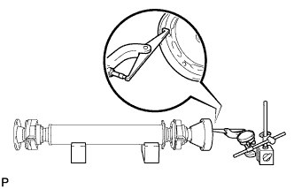
INSPECT SPIDER BEARING
-
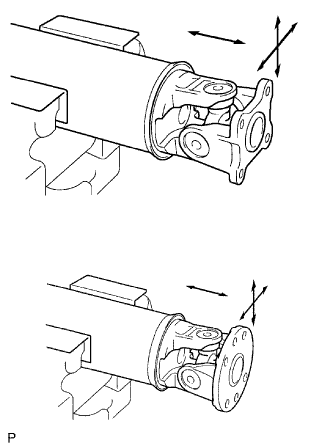
Check the spider bearing axial play by turning the flange while holding the shaft tightly.
Tech Tips
If necessary, replace the propeller with center bearing shaft assembly.
-
-
INSPECT INTERMEDIATE SHAFT
-
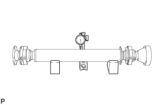
Using a dial indicator, inspect the runout of the intermediate shaft.
Maximum runout 0.4 mm (0.0157 in.) Note
The dial indicator must be set at a right angle to the center of the intermediate shaft.
Tech Tips
If the shaft runout exceeds the maximum, replace the propeller with center bearing shaft assembly.
-
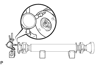
Using a dial indicator, inspect the runout of the front side of the intermediate shaft flange.
Maximum runout 0.1 mm (0.00393 in.) Tech Tips
If the intermediate shaft flange runout exceeds the maximum, replace the propeller with center bearing shaft assembly.
-
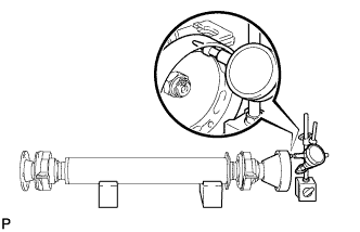
Using a dial indicator, inspect the runout of the rear side of the intermediate shaft flange in the horizontal direction.
Maximum runout 0.1 mm (0.00393 in.) Tech Tips
If the intermediate shaft flange runout exceeds the maximum, replace the propeller with center bearing shaft assembly.
-
Using a dial indicator, inspect the runout of the rear side of the intermediate shaft flange in the vertical direction.
Maximum runout 0.1 mm (0.00393 in.) Tech Tips
If the intermediate shaft flange runout exceeds the maximum, replace the propeller with center bearing shaft assembly.
-
-
INSPECT PROPELLER SHAFT
-

Using a dial indicator, inspect the runout of the propeller shaft.
Maximum runout 0.4 mm (0.0157 in.) Note
The dial indicator must be set at a right angle to the center of the intermediate shaft.
Tech Tips
If the shaft runout is greater than the maximum, replace the propeller with center bearing shaft assembly.
-
-
INSPECT REAR PROPELLER SHAFT
-

Using a dial indicator, inspect the runout of the rear propeller shaft.
Maximum runout 0.4 mm (0.0157 in.) Note
The dial indicator must be set at a right angle to the center of the intermediate shaft.
Tech Tips
If the shaft runout is greater than the maximum, replace the propeller with center bearing shaft assembly.
-
-
INSPECT NO. 2 CENTER SUPPORT BEARING ASSEMBLY
-

Turn the No. 2 center support bearing assembly by hand while applying force in the rotation direction. Check that the bearing turns smoothly.
-
Check that the seals are not cracked or damaged.
Tech Tips
If the No. 2 center support bearing assembly is damaged, worn, or does not turn freely, replace it.
-