REAR DRIVE SHAFT ASSEMBLY REASSEMBLY

-
INSTALL REAR DRIVE SHAFT DUST COVER
-
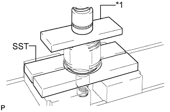
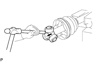
Text in Illustration *1 Steel Plate Using SST and a steel plate, install a new rear drive shaft dust cover.
- SST
- 09527-10011
Note
-
The rear drive shaft dust cover should be completely installed.
-
Be careful not to damage the rear drive shaft dust cover.
-
-
INSTALL REAR DRIVE SHAFT OUTBOARD JOINT BOOT
-
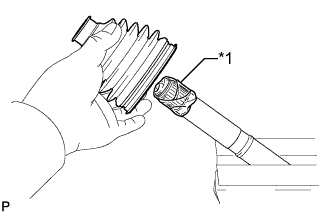
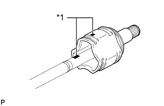
Text in Illustration *1 Protective Tape Wrap the splines of the drive shaft with protective tape to prevent the boot from being damaged.
-
Install new parts to the outboard joint shaft in the following order:
-
Rear drive shaft outboard joint boot clamp
-
Outboard joint boot
-
No. 2 rear drive shaft outboard joint boot clamp
-
-
Pack the outboard joint shaft assembly and outboard joint boot with grease from the boot kit.
Grease capacity 84 to 94 g (3.0 to 3.3 oz.)
-
-
INSTALL REAR DRIVE SHAFT OUTBOARD JOINT BOOT CLAMP
-
Hold the rear drive shaft in a vise between aluminum plates.
Note
Do not overtighten the vise.
-
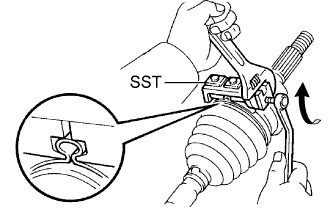
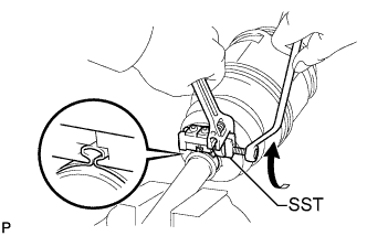
Secure the rear drive shaft outboard joint boot clamp onto the boot.
-
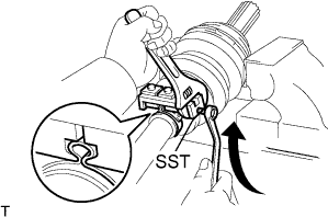
Place SST onto the rear drive shaft outboard joint boot clamp.
- SST
- 09521-24010
-
Tighten SST so that the rear drive shaft outboard joint boot clamp is pinched.
Note
Do not overtighten SST.
-
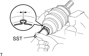
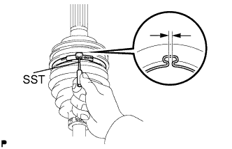
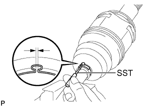
Using SST, inspect the clearance of the rear drive shaft outboard joint boot clamp.
- SST
- 09240-00020
Clearance 1.3 mm (0.0511 in.) or less Note
If the measured value exceeds the specified value, retighten the clamp.
-
-
INSTALL NO. 2 REAR DRIVE SHAFT OUTBOARD JOINT BOOT CLAMP
-
Hold the drive shaft in a vise between aluminum plates.
Note
Do not overtighten the vise.
-
Secure the outboard joint boot clamp onto the boot.
-
Place SST onto the No. 2 rear drive shaft outboard joint boot clamp.
- SST
- 09521-24010
-
Tighten SST so that the No. 2 rear drive shaft outboard joint boot clamp is pinched.
Note
Do not overtighten SST.
-
Using SST, inspect the clearance of the No. 2 rear drive shaft outboard joint boot clamp.
- SST
- 09240-00020
Clearance 1.3 mm (0.0511 in.) or less Note
If the measured value exceeds the specified value, retighten the clamp.
-
-
INSTALL REAR DRIVE SHAFT INBOARD JOINT ASSEMBLY
-
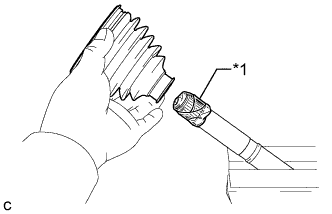
Text in Illustration *1 Protective Tape Wrap the splines of the drive shaft with protective tape to prevent the boot from being damaged.
-
Install new parts to the outboard joint shaft in the following order:
-
No. 2 rear drive shaft inboard joint boot clamp
-
Inboard joint boot
-
Rear drive shaft inboard joint boot clamp
-
-
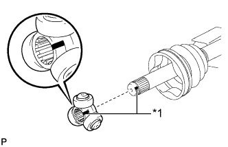
Text in Illustration *1 Matchmark Place the beveled side of the tripod joint axial spline toward the outboard joint shaft assembly.
-
Align the matchmarks placed before removal.
-
Using a brass bar and a hammer, tap the tripod joint onto the outboard joint shaft assembly.
Note
-
Do not tap the rollers.
-
Be sure to install the tripod joint in the correct direction.
-
-
Using a snap ring expander, install a new shaft snap ring.
-
Pack the outboard joint shaft and boot with grease.
Grease capacity 115 to 125 g (4.1 to 4.4 oz.) -
Text in Illustration *1 Matchmark Align the matchmarks, and install the inboard joint assembly to the outboard joint shaft assembly.
-
-
INSTALL REAR DRIVE SHAFT INBOARD JOINT BOOT
-
Install the rear drive shaft inboard joint boot to the outboard joint shaft.
-
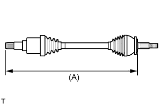
Check whether the drive shaft dimension (A) is within the following specification.
Dimension (A) 750.6 mm (2.46 ft.)
-
-
INSPECT REAR DRIVE SHAFT INBOARD JOINT BOOT CLAMP
-
Hold the rear drive shaft in a vise between aluminum plates.
Note
Do not overtighten the vise.
-
Secure the rear drive shaft inboard joint boot clamp onto the boot.
-
Place SST onto the rear drive shaft inboard joint boot clamp.
- SST
- 09521-24010
-
Tighten SST so that the rear drive shaft inboard joint boot clamp is pinched.
Note
Do not overtighten SST.
-
Using SST, inspect the clearance of the rear drive shaft inboard joint boot clamp.
- SST
- 09240-00020
Clearance 1.1 mm (0.0433 in.) or less Note
If the measured value exceeds the specified value, retighten the clamp.
-
-
INSTALL NO. 2 REAR DRIVE SHAFT INBOARD JOINT BOOT CLAMP
- SST
- 09521-24010
- 09240-00020
-
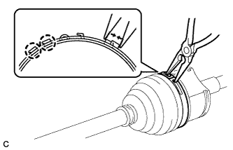
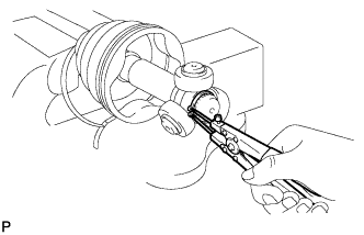
Using needle-nose pliers, install a new No. 2 rear drive shaft inboard joint boot clamp as shown in the illustration.
Note
Be careful not to damage the boot.
-
INSTALL REAR DRIVE SHAFT SNAP RING
-
Install a new rear drive shaft snap ring.
-
-
INSPECT REAR DRIVE SHAFT ASSEMBLY
-
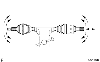
Check that there is no excessive play in the radial direction of the outboard joint.
-
Check that the inboard joint slides smoothly in the thrust direction.
-
Check that there is no excessive play in the radial direction of the inboard joint.
-
Check the boots for damage.
-
Check whether the drive shaft dimension (A) is within the following specification.
Dimension (A) 750.6 mm (2.46 ft.)
-