-
Use the same procedure for the RH side and LH side.
-
The procedure listed below is for the LH side.
- Click here
PRECAUTION (w/ Air Suspension)
Note:Be sure to read Precaution thoroughly before servicing (Click here).
- Click here
REMOVE FRONT WHEELS
- Click here
DRAIN AUTOMATIC TRANSAXLE FLUID
-
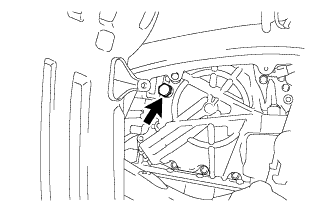
Remove the refill plug and gasket from the automatic transaxle.
-
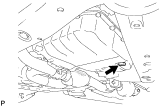
Using a 6 mm hexagon socket wrench, remove the overflow plug and gasket from the automatic transaxle.
-
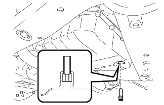
Using a 6 mm hexagon socket wrench, remove the No. 1 transmission oil filler tube from the automatic transaxle.
-
Drain automatic transaxle fluid from the automatic transaxle.
-
Using a 6 mm hexagon socket wrench, install the No. 1 transmission oil filler tube to the automatic transaxle.
1.7 N*m 17 kgf*cm 15 in.*lbf -
Using a 6 mm hexagon socket wrench, install a new gasket and the overflow plug to the automatic transaxle.
40 N*m 408 kgf*cm 30 ft.*lbf -
Temporarily install the gasket and the refill plug to the automatic transaxle.
-
- Click here
DRAIN TRANSFER OIL
-
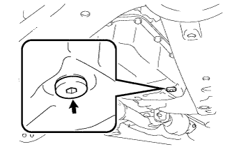
Remove the transfer drain plug and gasket to drain the transfer oil.
-
Install a new gasket and the transfer drain plug.
49 N*m 500 kgf*cm 36 ft.*lbf
-
- Click here
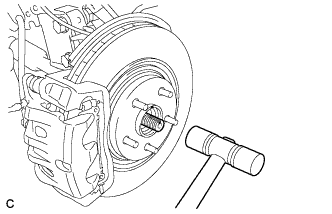
REMOVE FRONT AXLE SHAFT NUT
-
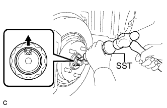
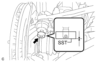
Using SST and a hammer, release the staked part of the front axle shaft nut.
09930-00010 Note:Loosen the staked part of the nut completely, otherwise the threads of the drive shaft may be damaged.
-
While applying the brakes, remove the front axle shaft nut.
-
- Click here
SEPARATE FRONT STABILIZER LINK ASSEMBLY
-
Remove the nut and separate the front stabilizer link assembly from the front shock absorber.
Tip:If the ball joint turns together with the nut, use a hexagon wrench (6 mm) to hold the stud bolt.
-
- Click here
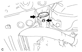
SEPARATE FRONT SPEED SENSOR
-
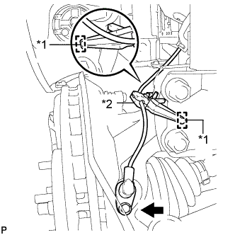
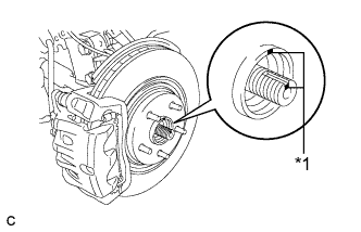
Remove the bolt and resin clamp, and separate the front speed sensor.
Table 1. Text in Illustration *1 Hole *2 Resin Clamp Note:
-
Be sure to completely separate the front speed sensor from the front shock absorber with coil spring.
-
Be careful not to damage the front speed sensor.
-
Clean the speed sensor installation hole and the surfaces every time the speed sensor is removed.
-
-
- Click here
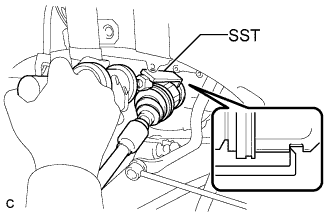
SEPARATE TIE ROD ASSEMBLY
-
Remove the cotter pin and nut.
-
Install SST to the tie rod end.
09960-20010 09961-02060 Note:Make sure that the upper ends of the tie rod end and SST are aligned.
-
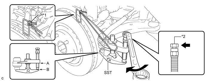
Using SST, separate the tie rod end from the steering knuckle.
Table 2. Text in Illustration *1 Tie the string without allowing for any slack. *2 Place the wrench here. 09960-20010 09961-02010 Note:
-
When securing SST to the steering knuckle, be sure to tighten SST using a string to prevent it from falling.
-
Install SST so that A and B are parallel.
-
Be sure to place a wrench on the part indicated in the illustration.
-
Do not damage the front disc brake dust cover.
-
Do not damage the ball joint dust cover.
-
Do not damage the steering knuckle.
-
-
- Click here
SEPARATE FRONT LOWER SUSPENSION ARM
-
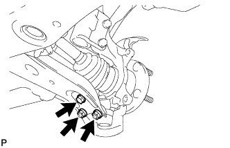
Remove the bolt and 2 nuts, and separate the front lower suspension arm from the lower ball joint.
-
- Click here
SEPARATE FRONT DRIVE SHAFT ASSEMBLY
-
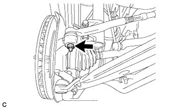
Put matchmarks on the front drive shaft assembly and the front axle hub sub-assembly.
Table 3. Text in Illustration *1 Matchmark -
Using a plastic hammer, separate the front drive shaft assembly from the front axle assembly.
Note:Loosen the staked part of the front axle hub nut completely, otherwise the threads of the drive shaft may be damaged.
-
- Click here
REMOVE FRONT DRIVE SHAFT ASSEMBLY LH
-
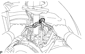
Using SST, remove the front drive shaft assembly LH.
09520-00031 09520-01010 Note:
-
Be careful not to damage the drive shaft dust cover, boot or oil seal.
-
Be careful not to drop the drive shaft assembly.
-
-
- Click here
REMOVE FRONT DRIVE SHAFT ASSEMBLY RH
-
Remove the bearing bracket hole snap ring from the drive shaft bearing bracket.
-
Remove the bolt and front drive shaft assembly RH from the drive shaft bearing bracket.
Note:Do not damage the boot or oil seal.
-