TRANSFER ASSEMBLY INSTALLATION

-
INSTALL PROPELLER SHAFT HEAT INSULATOR (w/ Heat Insulator)
-
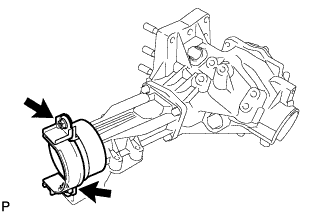
Install the propeller shaft heat insulator to the transfer assembly with the 2 nuts.
- Torque:
- 15 N*m { 153 kgf*cm, 11 ft.*lbf }
-
-
INSTALL TRANSFER ASSEMBLY
-
Install the 4 new transfer and transaxle setting stud bolts to the transaxle case positions shown in the illustration.
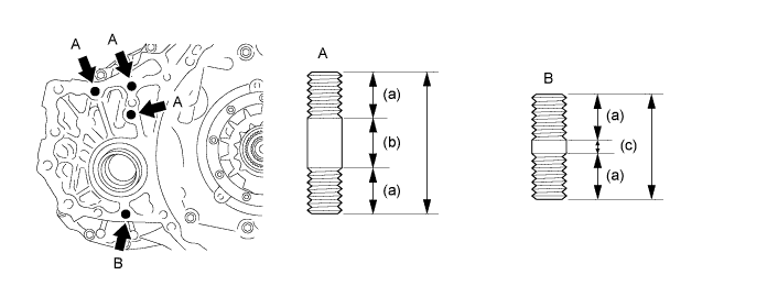
Stud bolt length a 22 mm (0.866 in.) b 25 mm (0.984 in.) c 5 mm (0.197 in.) - Torque:
- 39 N*m { 400 kgf*cm, 29 ft.*lbf }
Note
Install the sealed side of the stud bolt to the transaxle assembly.
-
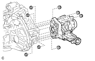
Install the transfer assembly to the transaxle assembly with the 8 nuts.
- Torque:
- 69 N*m { 700 kgf*cm, 51 ft.*lbf }
Note
-
Install the transfer assembly to the transaxle assembly horizontally.
-
Do not touch the transfer assembly oil seals during installation.
-
-
INSTALL AUTOMATIC TRANSAXLE ASSEMBLY
-
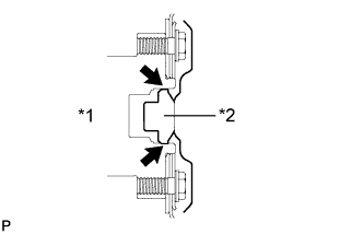
Text in Illustration *1 Crankshaft *2 Torque Converter Assembly Centerpiece Apply clutch spline grease to the round of the crankshaft contact surface with the torque converter assembly centerpiece.
Clutch spline grease Toyota Genuine Clutch Spline Grease or equivalent Maximum spread About 1 g (0.0353 oz.) -
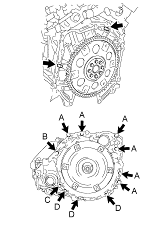
Keeping the engine and automatic transaxle assembly in a horizontal position, align the knock pins with each hole on the automatic transaxle assembly and tighten the 11 bolts shown in the illustration.
- Torque:
- Bolt A
- 64 N*m { 653 kgf*cm, 47 ft.*lbf }
- Bolt B
- 64 N*m { 653 kgf*cm, 47 ft.*lbf }
- Bolt C
- 46 N*m { 469 kgf*cm, 34 ft.*lbf }
- Bolt D
- 43 N*m { 439 kgf*cm, 32 ft.*lbf }
Note
-
Confirm that the 2 knock pins are on the transaxle contact surface of the engine cylinder block before transaxle installation.
-
Do not forcibly pry on the automatic transaxle assembly.
-
Check that the torque converter assembly rotates.
Tech Tips
Bolt length:
-
Bolt A: 55 mm (2.17 in.)
-
Bolt B: 50 mm (1.97 in.)
-
Bolt C: 41 mm (1.61 in.)
-
Bolt D: 33 mm (1.30 in.)
-
-
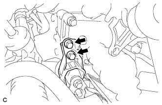
INSTALL TRANSFER STIFFENER PLATE RH
-
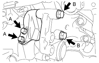
Install the transfer stiffener plate RH with the 4 bolts.
- Torque:
- Bolt A
- 34 N*m { 347 kgf*cm, 25 ft.*lbf }
- Bolt B
- 78 N*m { 796 kgf*cm, 58 ft.*lbf }
-
-
INSTALL WIRE HARNESS
-
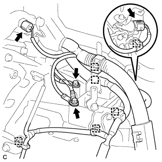
Connect the 6 wire harness clamps and 2 connectors.
-
Install the 2 wire harnesses with the 2 bolts.
- Torque:
- 19 N*m { 195 kgf*cm, 14 ft.*lbf }
-
-
INSTALL TCM
-
Install the TCM to the transaxle.
-
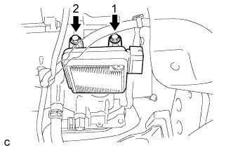
Install and tighten the 2 bolts in the order shown in the illustration.
- Torque:
- 11 N*m { 115 kgf*cm, 8 ft.*lbf }
-
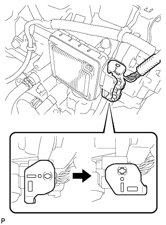
Connect the connector to the TCM.
-
Turn the lock lever and secure the connector with the lock lever.
-
-
INSTALL MANIFOLD STAY
-
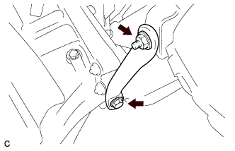
Install the manifold stay with the bolt and nut.
- Torque:
- Bolt
- 34 N*m { 347 kgf*cm, 25 ft.*lbf }
- Nut
- 35 N*m { 357 kgf*cm, 26 ft.*lbf }
-
-
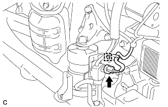
INSTALL RADIATOR PIPE CLAMP
-
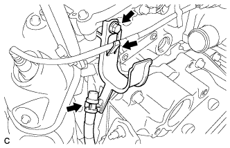
Install the radiator pipe clamp with the bolt.
- Torque:
- 5.5 N*m { 56 kgf*cm, 49 in.*lbf }
-
Install the sensor wire and the breather plug hose to the radiator pipe clamp.
-
-
INSTALL STARTER ASSEMBLY
-
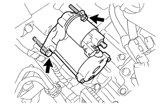
Install the starter with the 2 bolts.
- Torque:
- 37 N*m { 377 kgf*cm, 27 ft.*lbf }
-
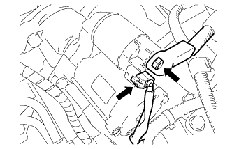
Connect the starter connector.
-
Install the terminal nut and cover the nut with the cap.
- Torque:
- 9.8 N*m { 100 kgf*cm, 87 in.*lbf }
-
-
INSTALL FRONT FRAME ASSEMBLY
-
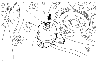
Install the engine mounting insulator RH with the nut.
- Torque:
- 95 N*m { 969 kgf*cm, 70 ft.*lbf }
-
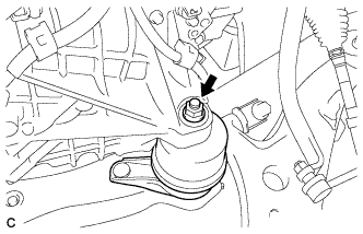
Install the engine mounting insulator LH with the nut.
- Torque:
- 95 N*m { 969 kgf*cm, 70 ft.*lbf }
-
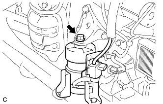
Install the front engine mounting insulator with the bolt.
- Torque:
- 87 N*m { 888 kgf*cm, 65 ft.*lbf }
-
Connect the wire clamp and connector.
-
Install the rear engine mounting insulator assembly with the 2 bolts.
- Torque:
- 78 N*m { 795 kgf*cm, 57 ft.*lbf }
-
-
INSTALL STEERING LINK ASSEMBLY
-
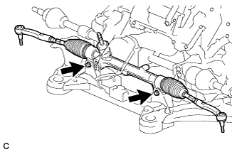
Install the power steering link assembly with the 2 bolts and 2 nuts.
- Torque:
- 70 N*m { 713 kgf*cm, 51 ft.*lbf }
Note
-
Make sure to tighten the bolts starting from the steering link assembly pinion shaft side.
-
Because the nut has its own stopper, do not turn the nut. Tighten the bolt with the nut secured.
-
-
INSTALL FRONT STABILIZER BAR WITH FRONT STABILIZER LINK ASSEMBLY
-
INSTALL FRONT NO. 1 STABILIZER BRACKET LH
-
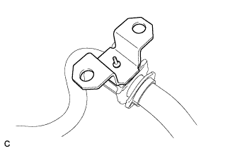
Install the front No. 2 stabilizer bracket LH to the front No. 1 stabilizer bar bushing.
-
-
INSTALL FRONT NO. 1 STABILIZER BRACKET RH
Tech Tips
Perform the same procedure as for the LH side.
-
INSTALL ENGINE ASSEMBLY WITH TRANSAXLE
Tech Tips
See the steps from "Install Engine Assembly with Transaxle" through "Engine Room Side Cover LH" Click here.