TRANSFER ASSEMBLY INSPECTION

-
INSPECT PRELOAD
-
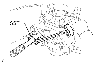
Using SST and a torque wrench, measure the preload of the backlash between the driven pinion and ring gear.
- SST
- 09326-20011
Preload (at Starting) Item Preload without SST 0.5 to 0.9 N*m (5 to 9 kgf*cm, 4 to 8 in.*lbf) with SST 0.3 to 0.6 N*m (3 to 6 kgf*cm, 3 to 5 in.*lbf) Note
-
The "with SST" torque value is effective when using SST with a fulcrum length of 50 mm (1.97 in.).
-
The "with SST" torque value is effective when using a torque wrench with a fulcrum length of 130 mm (5.12 in.) Click here.
-
The "with SST" torque value is effective when SST is parallel to the torque wrench.
-
Using SST and a torque wrench, measure the total preload.
- SST
- 09326-20011
Preload (at Starting) Item Preload without SST 0.4 to 0.5 N*m (4 to 5 kgf*cm, 3 to 4 in.*lbf) + driven pinion preload with SST 0.25 to 0.38 N*m (2.6 to 3.8 kgf*cm, 2.3 to 3.3 in.*lbf) + driven pinion preload Note
-
The "with SST" torque value is effective when using SST with a fulcrum length of 50 mm (1.97 in.).
-
The "with SST" torque value is effective when using a torque wrench with a fulcrum length of 130 mm (5.12 in.) Click here.
-
The "with SST" torque value is effective when SST is parallel to the torque wrench.
-
-
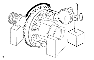
INSPECT RING GEAR BACKLASH
-
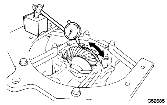
Using a dial indicator, check the backlash of the ring gear.
Backlash 0.14 to 0.25 mm (0.00551 to 0.00984 in.) If the backlash is not within the specification, adjust the side bearing preload or repair as necessary.
Note
Check at least 3 positions on the circumference of the ring gear.
-
-
INSPECT TOOTH CONTACT BETWEEN RING GEAR AND DRIVEN PINION
-
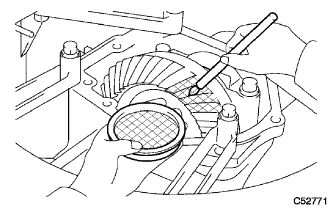
Coat 3 or 4 teeth at 4 different positions on the ring gear with Prussian blue.
-
Rotate the ring gear 10 times or more.
-
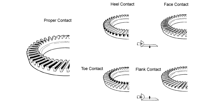
Rotate the ring gear to inspect the tooth contact pattern.
-
If the tooth contact pattern is not correct, select a new transfer output shaft washer that is thicker or thinner as necessary and recheck.
-
-
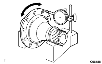
INSPECT RING GEAR RUNOUT
-
Place the transfer ring gear mounting case on the V-blocks.
-
Using a dial indicator, check the runout of the ring gear.
Maximum runout 0.06 mm (0.00236 in.)
-
-
INSPECT TRANSFER RING GEAR MOUNTING CASE RUNOUT
-
Place the transfer ring gear mounting case on the V-blocks.
-
Using a dial indicator, check the runout of the ring gear mounting case.
Maximum runout 0.04 mm (0.00157 in.)
-