ACTIVE TORQUE CONTROL 4WD SYSTEM AWD Control Switch Circuit
DESCRIPTION
An AWD Lock Switch (4 Wheel Drive Control Switch) has been provided.
This enables the driver to select between the AUTO and LOCK modes by operating the switch.
The system optimally controls the torque distribution to the front and rear wheels in the respective modes.
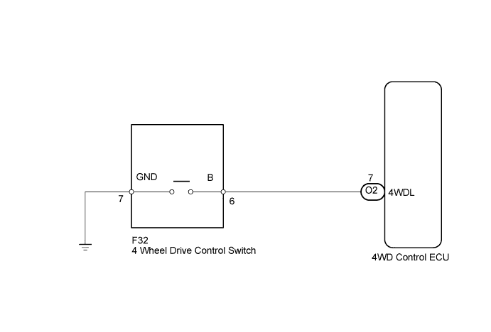
WIRING DIAGRAM
INSPECTION PROCEDURE
PROCEDURE
-
INSPECT 4 WHEEL DRIVE CONTROL SWITCH
-
Disconnect the connector of 4 wheel drive control switch Click here.
-

Text in Illustration *1 Component without harness connected
(4 Wheel Drive Control Switch)
Measure the resistance according to the value(s) in the table below.
Standard Resistance Tester Connection Condition Specified Condition 6 (B) - 7 (GND) Press continuously 4 Wheel Drive Control Switch Below 1 Ω Release 4 Wheel Drive Control Switch 10 kΩ or higher
NG 
REPLACE 4 WHEEL DRIVE CONTROL SWITCH Click here
OK 
-
-
CHECK HARNESS AND CONNECTOR (4WD ECU - BODY GROUND)
-
Connect the connector of 4 wheel drive control switch.
-
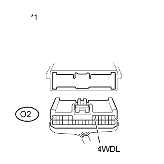
Text in Illustration *1 Rear view of wire harness connector
(to 4WD Control ECU)
Disconnect the ECU connector.
-
Measure the resistance of the wire harness side connector.
Standard Resistance Tester Connection Condition Specified Condition O2-7 (4WDL) - Body Ground Press continuously 4 Wheel Drive Control Switch Below 1 Ω Release 4 Wheel Drive Control Switch 10 kΩ or higher Result Result Proceed to OK (for LHD) A OK (for RHD) B NG C
B
REPLACE 4WD ECU ASSEMBLY (for RHD) Click here
C
REPAIR OR REPLACE HARNESS OR CONNECTOR
A 
REPLACE 4WD ECU ASSEMBLY (for LHD) Click here
-