ACTIVE TORQUE CONTROL 4WD SYSTEM Warning Light Circuit
DESCRIPTION
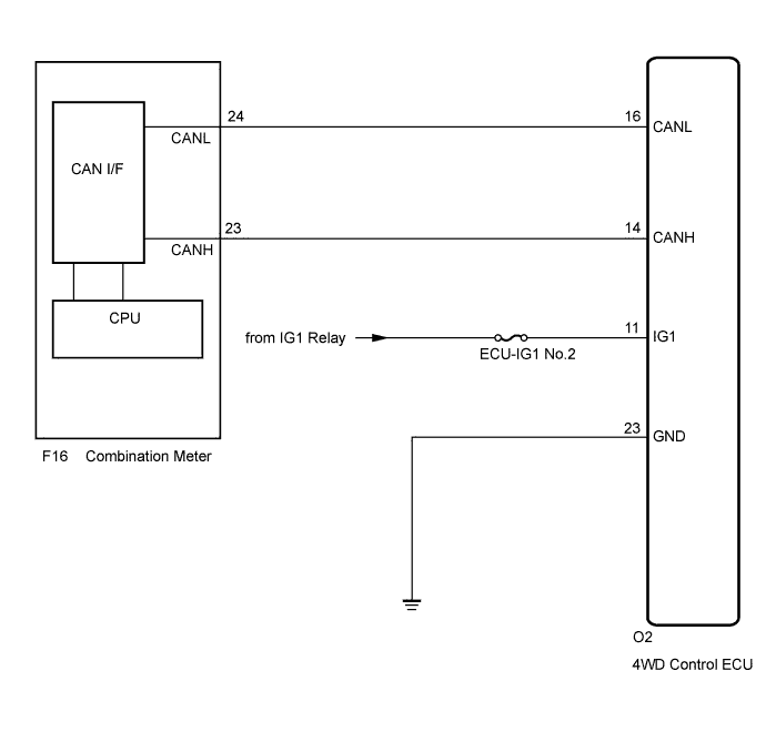
The 4WD control ECU is connected to the combination meter via the CAN communication system.
If the 4WD control ECU stores any DTCs which are related to the active torque control 4WD system, the AWD warning light comes on in the combination meter.
WIRING DIAGRAM
INSPECTION PROCEDURE
Tech Tips
Check the condition of each related circuit connector before troubleshooting Click here.
PROCEDURE
-
CHECK FOR DTC
-
Check if the CAN communication system DTC is output Click here.
-
Check if the 4WD control system DTC is output Click here.
Result Result Proceed to Neither CAN communication system DTC nor 4WD control system DTC is output A CAN communication DTC is output B 4WD control system DTC is output C Tech Tips
When DTCs indicating a CAN communication system malfunction are output, repair the CAN communication system before repairing each corresponding sensor.
B 
REPAIR CIRCUIT INDICATOR BY OUTPUT CODE (CAN COMMUNICATION SYSTEM) Click here
C
REPAIR CIRCUIT INDICATOR BY OUTPUT CODE (ACTIVE TORQUE CONTROL 4WD SYSTEM) Click here
A 
-
-
CHECK IF 4WD ECU CONNECTOR IS SECURELY CONNECTED
-
Check if the skid control ECU connector is securely connected.
OK The connector is securely connected.
NG
CONNECT CONNECTOR TO ECU CORRECTLY
OK
-
-
CHECK BATTERY
-
Check the battery voltage.
Standard Voltage 11 to 14 V
NG
INSPECT CHARGING SYSTEM
OK
-
-
PERFORM ACTIVE TEST (4WD WARNING LIGHT)
-
Warm up the engine.
-
Turn the engine switch off.
-
Connect the intelligent tester to the DLC3.
-
Turn the engine switch on (IG).
-
Turn the intelligent tester on.
-
Enter the following menus: Chassis / 4WD / Active Test.
-
According to the display on the intelligent tester, perform the Active Test.
Chassis / 4WD / Active Test Tester Display Test Part Control Range Diagnostic Note 4WD Warning Light Master Warning Light and Multi-information Display ON: Master warning light and Multi-information display on
OFF: Master warning light and Multi-information display off
Observe combination meter OK The warning light turns off. Result Result Proceed to OK (for LHD) A OK (for RHD) B NG C
B
REPLACE 4WD ECU ASSEMBLY (for RHD) Click here
C 
CHECK WIRE HARNESS OR CONNECTOR (4WD ECU - BATTERY) Click here
A 
REPLACE 4WD ECU ASSEMBLY (for LHD) Click here
-
-
CHECK WIRE HARNESS OR CONNECTOR (4WD ECU - BATTERY)
-
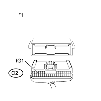
Text in Illustration *1 Rear view of wire harness connector
(to 4WD Control ECU)
Disconnect the ECU connector.
-
Turn the engine switch on (IG).
-
Measure the voltage of the wire harness side connector.
Standard Voltage Tester Connection Condition Specified Condition O2-11 (IG1) - Body Ground Engine switch on (IG) 11 to 14 V
NG
REPAIR OR REPLACE HARNESS OR CONNECTOR
OK
-
-
CHECK WIRE HARNESS OR CONNECTOR (4WD ECU - BODY GROUND)
-
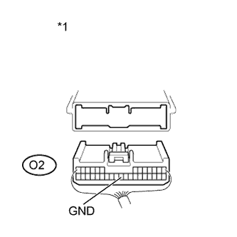
Text in Illustration *1 Rear view of wire harness connector
(to 4WD Control ECU)
Disconnect the ECU connector.
-
Measure the resistance of the wire harness side connector.
Standard Resistance Tester Connection Condition Specified Condition O2-23 (GND) - Body Ground Always Below 1 Ω
NG
REPAIR OR REPLACE HARNESS OR CONNECTOR
OK
GO TO METER / GAUGE SYSTEM Click here
-