ACTIVE TORQUE CONTROL 4WD SYSTEM, Diagnostic DTC:C1297

| DTC Code | DTC Name |
|---|---|
| C1297 | Steering Angle Sensor |
DESCRIPTION
-
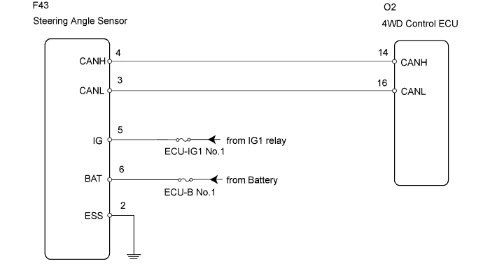
The 4WD control ECU determines that the vehicle is turning based on the signals sent from the steering angle sensor.
-
The steering angle sensor signal is sent to the 4WD control ECU via the CAN communication system.
-
The 4WD control ECU detects the amount of steering wheel movement and performs "slip control at vehicle start up", according to the amount of movement, and "slip control" to secure high turning performance.
| DTC No. | DTC Detection Condition | Trouble Area |
|---|---|---|
| C1297 | When voltage of 4WD control ECU IG terminal is 9.5 V or more, and steering angle sensor malfunction signal is received. |
|
WIRING DIAGRAM
INSPECTION PROCEDURE
Tech Tips
Check the condition of each related circuit connector before troubleshooting Click here.
PROCEDURE
-
CHECK FOR DTC
-
Clear the DTC Click here.
-
Turn the engine switch off.
-
Turn the engine switch on (IG) again and check that no CAN communication system DTC(s) is output Click here.
-
Start the engine.
-
Drive the vehicle and turn the steering wheel to the right and left at a speed of 35 km/h (24 mph) and check that no brake control system (steering angle sensor) DTC (C1432,C1433 or C1434) is output Click here.
Result Result Proceed to Neither CAN communication system DTC nor brake control system DTC is output A CAN communication system DTC is output B Brake control system (steering angle sensor) DTC (C1432,C1433 or C1434) is output C Tech Tips
When DTCs indicating a CAN communication system malfunction are output, repair the CAN communication system before repairing each corresponding sensor.
B 
REPAIR CIRCUIT INDICATOR OUTPUT CODE (CAN COMMUNICATION SYSTEM) Click here
C
REPAIR OR REPLACE CIRCUIT INDICATOR OUTPUT CODE (STEERING ANGLE SENSOR CIRCUIT) Click here
A 
-
-
CHECK WIRE HARNESS (STEERING ANGLE SENSOR - BATTERY)
-
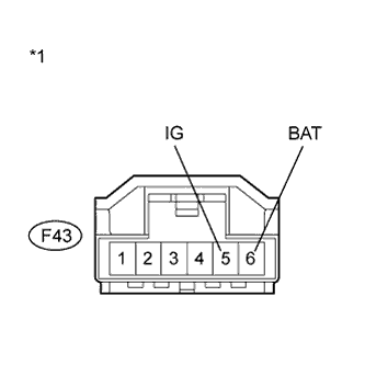
Text in Illustration *1 Front view of wire harness connector
(to Steering Angle Sensor)
Remove the steering wheel and the column cover lower.
-
Make sure that there is no looseness at the locking part and the connecting part of the connectors.
-
Disconnect the steering angle sensor connector.
-
Measure the voltage according to the value(s) in the table below.
Standard Voltage Tester Connection Condition Specified Condition F43-5 (IG) - Body ground Engine switch on (IG) 11 to 14 V F43-6 (BAT) - Body ground Always 11 to 14 V
NG
REPAIR OR REPLACE HARNESS AND CONNECTOR
OK
-
-
CHECK WIRE HARNESS (STEERING ANGLE SENSOR - BODY GROUND)
-
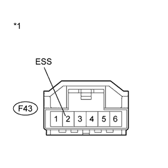
Text in Illustration *1 Front view of wire harness connector
(to Steering Angle Sensor)
Turn the engine switch off.
-
Measure the resistance according to the value(s) in the table below.
Standard Resistance Tester Connection Condition Specified Condition F43-2 (ESS) - Body ground Always Below 1 Ω
NG
REPAIR OR REPLACE HARNESS AND CONNECTOR
OK 
REPLACE SPIRAL CABLE (STEERING ANGLE SENSOR) Click here
-