ACTIVE TORQUE CONTROL 4WD SYSTEM, Diagnostic DTC:C1241

| DTC Code | DTC Name |
|---|---|
| C1241 | Low Power Supply Voltage Malfunction |
DESCRIPTION
If a malfunction in the power source circuit occurs, or a malfunction in communication with the skid control ECU or in a speed sensor occurs, the 4WD control ECU will prohibit operations by the fail-safe function.
| DTC No. | DTC Detection Condition | Trouble Area |
|---|---|---|
| C1241 |
|
|
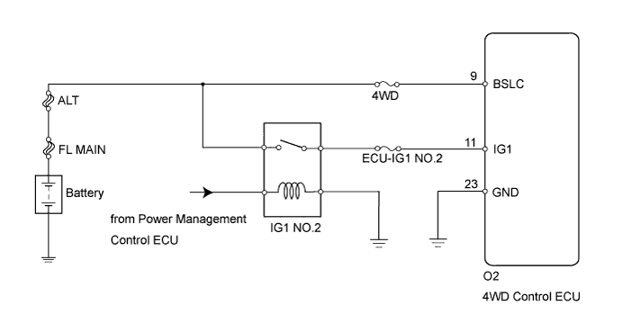
WIRING DIAGRAM
INSPECTION PROCEDURE
Note
Inspect the fuses for circuits related to this system before performing the following inspection procedure.
Tech Tips
Check the condition of each related circuit connector before troubleshooting Click here.
PROCEDURE
-
CHECK FOR DTC (CAN COMMUNICATION SYSTEM AND BRAKE CONTROL SYSTEM)
-
Check if the CAN communication system DTC is output Click here.
-
Start the engine.
-
Drive the vehicle, accelerate to a speed of 3 km/h (2 mph) or more, and check if the speed sensor DTC (brake control system DTC) is output Click here.
Result Result Proceed to Neither CAN communication system DTC nor speed sensor DTC (brake control system DTC) is output A CAN communication system DTC is output B Speed sensor DTC (brake control system DTC) is output C
B 
REPAIR CIRCUIT INDICATOR BY OUTPUT CODE (CAN COMMUNICATION SYSTEM) Click here
C
REPAIR CIRCUIT INDICATOR BY OUTPUT CODE (BRAKE CONTROL SYSTEM) Click here
A 
-
-
INSPECT BATTERY
-
Check the battery voltage.
Standard Voltage 11 to 14 V
NG
INSPECT CHARGING SYSTEM
OK
-
-
CHECK WIRE HARNESS (4WD CONTROL ECU - BATTERY)
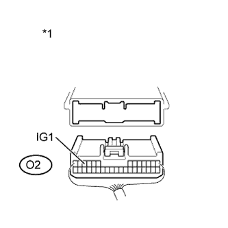
Text in Illustration *1 Rear view of wire harness connector
(to 4WD Control ECU)
-
Disconnect the ECU connector.
-
Measure the voltage of the wire harness side connector.
Standard Voltage Tester Connection Switch Condition Specified Condition O2-11 (IG1) - Body Ground Engine switch on (IG) 10 to 14 V
NG
REPAIR OR REPLACE HARNESS OR CONNECTOR
OK
-
-
CHECK WIRE HARNESS (4WD CONTROL ECU - BODY GROUND)
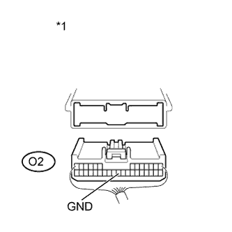
Text in Illustration *1 Rear view of wire harness connector
(to 4WD Control ECU)
-
Disconnect the ECU connector.
-
Measure the resistance of the wire harness side connector.
Standard Resistance Tester Connection Condition Specified Condition O2-23 (GND) - Body Ground Always Below 1 Ω
NG
REPAIR OR REPLACE HARNESS OR CONNECTOR
OK
-
-
RECONFIRM DTC
-
Clear the DTC Click here.
-
Start the engine.
-
Drive the vehicle, accelerate to a speed of 3 km/h (2 mph or more, and check if the same DTC is output.
Result Result Proceed to DTC is output (for LHD) A DTC is output (for RHD) B DTC is not output C Tech Tips
Reinstall the sensor, connectors, etc. and restore the vehicle to its prior condition before rechecking DTCs.
B
REPLACE 4WD ECU ASSEMBLY (for RHD) Click here
C
CHECK INTERMITTENT PROBLEMS
A 
REPLACE 4WD ECU ASSEMBLY (for LHD) Click here
-