ACTIVE TORQUE CONTROL 4WD SYSTEM TERMINALS OF ECU

-
CHECK 4WD ECU
-
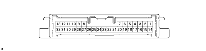
Measure the voltage and resistance of the connector.
Terminal No. (Symbol) Terminal Description Condition Specified Condition 7 (4WDL) - Body ground 4 wheel drive control switch signal Engine switch on (IG) and Press continuously 4 wheel drive control switch ON Below 1 V 14 (CANH) - 16 (CANL) CAN communication Engine switch off 54 to 69 Ω 23 (GND) - Body ground Ground Engine switch off Below 1 Ω 11 (IG1) - 23 (GND) Power source voltage Engine switch on (IG) 10 to 14 V 13 (SLC+) - 32 (SLC-) 4WD linear solenoid signal D position, Idling Pulse generation (See waveform 1) 9 (BSLC) - 23 (GND) Power source voltage Always 10 to 14 V If the result is not as specified, the 4WD ECU may have a malfunction.
-
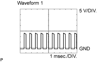
Using an oscilloscope, check the waveform 1.
Waveform 1 (Reference) Terminal Name Content Tester Range 5 V/DIV., 1 msec./DIV. Condition D position, Idling
-