FRONT DRIVE SHAFT ASSEMBLY (for 1AR-FE) INSTALLATION

-
INSTALL FRONT DRIVE SHAFT ASSEMBLY LH
-
Align the shaft splines and install the drive shaft assembly LH with a brass bar and a hammer.
Note
-
Set the shaft snap ring with the opening facing down.
-
Be careful not to damage the drive shaft dust cover, boot or oil seal.
-
When inserting the drive shaft assembly, keep it level.
-
-
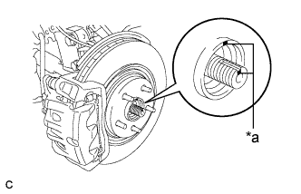
Text in Illustration *a Matchmark Align the matchmarks and install the front drive shaft assembly LH to the front axle hub sub-assembly.
-
-
INSTALL FRONT DRIVE SHAFT ASSEMBLY RH
-
Install the front drive shaft assembly RH.
-
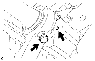
Install a new bearing bracket hole snap ring and the bolt.
- Torque:
- 32 N*m { 330 kgf*cm, 24 ft.*lbf }
Note
-
Do not damage the boot or oil seal.
-
When inserting the drive shaft assembly, keep it level.
-
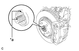
Text in Illustration *a Matchmark Align the matchmarks and install the front drive shaft assembly RH to the front axle hub sub-assembly.
-
-
INSTALL FRONT LOWER SUSPENSION ARM
-
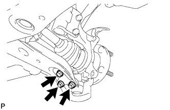
Install the front lower suspension arm to the front lower ball joint with the bolt and 2 nuts.
- Torque:
- 92 N*m { 938 kgf*cm, 68 ft.*lbf }
-
-
INSTALL TIE ROD ASSEMBLY
-
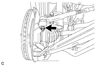
Connect the tie rod assembly LH to the steering knuckle with the nut.
- Torque:
- 49 N*m { 500 kgf*cm, 36 ft.*lbf }
-
Install a new cotter pin.
Note
Further tighten the nut up to 60° if the holes for the cotter pin are not aligned.
-
-
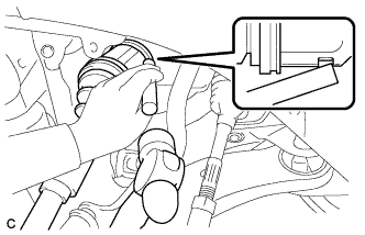
INSTALL FRONT SPEED SENSOR
-
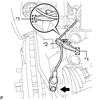
Text in Illustration *1 Hole *2 Resin Clamp Install the resin clamp and front speed sensor with the bolt.
- Torque:
- 8.5 N*m { 87 kgf*cm, 75 in.*lbf }
Note
-
Prevent foreign matter from attaching to the sensor tip.
-
Firmly insert the sensor body into the knuckle before tightening the bolt.
-
After installing the sensor to the knuckle, make sure that there is no clearance between the sensor stay and knuckle. Also make sure that no foreign matter is stuck between the parts.
-
To prevent interference between the sensor and magnetic rotor, do not rotate the sensor body during or after the insertion of the sensor body to the knuckle.
-
-
INSTALL FRONT STABILIZER LINK ASSEMBLY
-
Install the front stabilizer link assembly to the front shock absorber with the nut.
- Torque:
- 74 N*m { 755 kgf*cm, 55 ft.*lbf }
Tech Tips
If the ball joint turns together with the nut, use a hexagon wrench (6 mm) to hold the stud bolt.
-
-
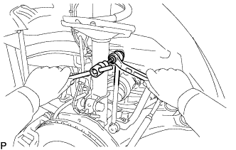
INSTALL FRONT AXLE SHAFT NUT
-
Clean the threaded parts on the drive shaft and a new axle shaft nut using a non-residue solvent.
Tech Tips
-
Be sure to perform this work for a new drive shaft.
-
Keep the threaded parts free of oil and foreign objects.
-
-
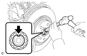
Using a socket wrench (30 mm), install the axle shaft nut.
- Torque:
- 294 N*m { 2998 kgf*cm, 217 ft.*lbf }
-
Using a chisel and hammer, stake the front axle shaft nut.
-
-
INSTALL FRONT WHEELS
- Torque:
- 103 N*m { 1050 kgf*cm, 76 ft.*lbf }
-
ADD AUTOMATIC TRANSAXLE FLUID
-
INSPECT FOR AUTOMATIC TRANSAXLE FLUID LEAK
-
ADJUST FRONT WHEEL ALIGNMENT
-
CHECK ABS SPEED SENSOR SIGNAL