AUTOMATIC TRANSAXLE ASSEMBLY INSTALLATION

-
INSTALL TRANSMISSION CASE PLUG ASSEMBLY
-
Apply ATF to a new O-ring and install it onto the transmission case plug.
-
Install the transmission case plug onto the automatic transaxle.
-
-
INSTALL NO. 1 TRANSMISSION CONTROL CABLE BRACKET
-
Install the No. 1 transmission control cable bracket onto the automatic transaxle with the 2 bolts.
- Torque:
- 12 N*m { 122 kgf*cm, 9 ft.*lbf }
-
-
INSTALL WIRE HARNESS CLAMP BRACKET
-
Install the 4 wire harness clamp brackets onto the automatic transaxle with the 4 bolts.
- Torque:
- 8.4 N*m { 85 kgf*cm, 74 in.*lbf }
-
-
INSTALL FRONT ENGINE MOUNTING BRACKET
-
Install the front engine mounting bracket onto the automatic transaxle with the 3 bolts.
- Torque:
- 64 N*m { 653 kgf*cm, 47 ft.*lbf }
-
-
INSTALL FLEXIBLE HOSE BRACKET SUB-ASSEMBLY
-
Install the flexible hose bracket onto the automatic transaxle with the bolt.
- Torque:
- 20 N*m { 204 kgf*cm, 15 ft.*lbf }
-
-
CONNECT BREATHER PLUG HOSE
-
Engage the clamp and connect the breather plug hose onto the flexible hose bracket.
-
-
INSTALL TORQUE CONVERTER ASSEMBLY
-
Engage the splines of the input shaft and turbine runner.
-
Engage the splines of the stator shaft and the stator while turning the torque converter assembly.
Tech Tips
If the stator shaft splines are difficult to engage with the stator splines, move the torque converter assembly back approximately 10 mm (0.393 in.) and engage the splines while rotating the torque converter assembly.
-
Turn the torque converter assembly to engage the key of the oil pump drive gear into the slot on the torque converter assembly.
-
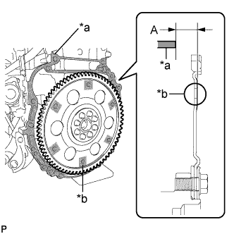
Text in Illustration *a Transaxle Contact Surface *b Torque Converter Assembly Contact Surface Using a vernier caliper and a straightedge, measure dimension A between the transaxle contact surface of the engine (*a) and the torque converter assembly contact surfaces of the drive plate (*b). [#1]
-
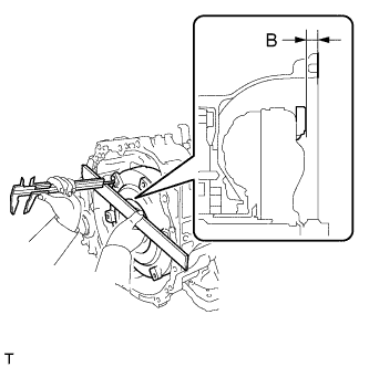
Using a vernier caliper and a straightedge, measure dimension B shown in the illustration and check that dimension B is greater than dimension A, which was measured in step [#1].
Standard B = A + 1 mm (0.0394 in.) or more Note
-
Make sure to deduct the thickness of the straightedge.
-
If the transaxle is installed to the engine with the torque converter assembly not sufficiently inserted, the torque converter assembly may be damaged.
-
-
-
INSTALL AUTOMATIC TRANSAXLE ASSEMBLY
-
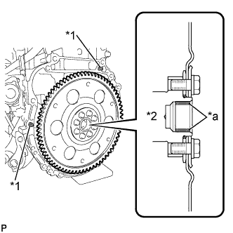
Text in Illustration *1 Knock Pin Confirm that the 2 knock pins are on the automatic transaxle contact surface of the engine cylinder block before automatic transaxle installation.
-
Apply clutch spline grease to the circumference of the crankshaft contact surface (*a) with the torque converter assembly centerpiece.
Clutch spline grease Toyota Genuine Clutch Spline Grease or equivalent Maximum spread Approximately 1 g (0.0353 oz) -
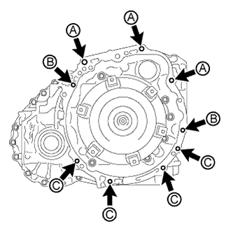
Text in Illustration *2 Crankshaft *a Crankshaft Contact Surface Keeping the engine and automatic transaxle in a horizontal position, align the knock pins with each hole on the automatic transaxle and tighten the 9 bolts shown in the illustration.
- Torque:
- Bolt A
- 64 N*m { 653 kgf*cm, 47 ft.*lbf }
- Bolt B
- 46 N*m { 469 kgf*cm, 34 ft.*lbf }
- Bolt C
- 43 N*m { 438 kgf*cm, 32 ft.*lbf }
Bolt Length Bolt Length [mm (in.)] A 55 (2.17) B 50 (1.97) C 33 (1.30) Note
-
Do not twist or apply excessive force to the automatic transaxle.
-
Check that the torque converter assembly rotates smoothly after installation of the automatic transaxle.
-
-
CONNECT ENGINE WIRE
-
Engage the 5 clamps and connect the engine wire.
-
Install the engine wire onto the automatic transaxle with the 2 bolts.
- Torque:
- 19 N*m { 195 kgf*cm, 14 ft.*lbf }
-
-
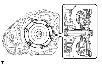
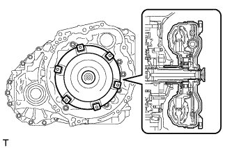
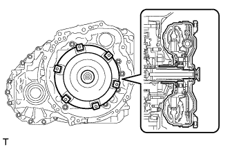
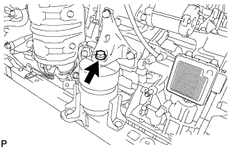
INSTALL TCM
-
Install the TCM to the transaxle.
-
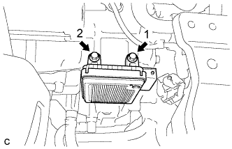
Install and tighten the 2 bolts in the order shown in the illustration.
- Torque:
- 11 N*m { 115 kgf*cm, 8 ft.*lbf }
-
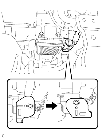
Connect the connector to the TCM.
-
Turn the lock lever and secure the connector with the lock lever.
-
-
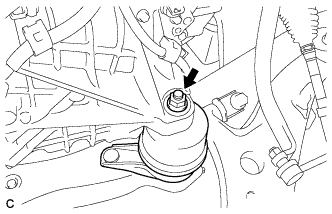
INSTALL STARTER ASSEMBLY
-
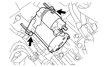
Install the starter with the 2 bolts.
- Torque:
- 37 N*m { 377 kgf*cm, 27 ft.*lbf }
-
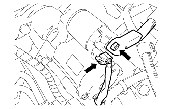
Connect the starter connector.
-
Install the starter wire with the nut and cover the nut with the cap.
- Torque:
- 9.8 N*m { 100 kgf*cm, 87 in.*lbf }
-
-
INSTALL FRONT FRAME ASSEMBLY
-
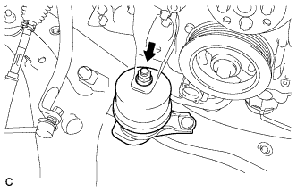
Install the engine mounting insulator RH with the nut.
- Torque:
- 95 N*m { 969 kgf*cm, 70 ft.*lbf }
-
Install the engine mounting insulator LH with the nut.
- Torque:
- 95 N*m { 969 kgf*cm, 70 ft.*lbf }
-
Install the front engine mounting insulator with the bolt.
- Torque:
- 87 N*m { 888 kgf*cm, 65 ft.*lbf }
-
Fully tighten the 9 temporarily installed nuts of the engine mounting insulators to the specified torque.
Tech Tips
Perform this procedure only when replacement of the engine mounting insulator is necessary.
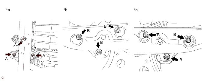
Text in Illustration *a Front Engine Mounting Insulator *b Engine Mounting Insulator RH *c Engine Mounting Insulator LH - - - Torque:
- A
- 52 N*m { 531 kgf*cm, 38 ft.*lbf }
- Torque:
- B
- 87 N*m { 888 kgf*cm, 64 ft.*lbf }
-
Install the 5 hole plugs.
Tech Tips
Perform this procedure only when replacement of the engine mounting insulator is necessary.
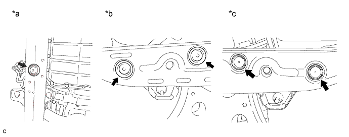
Text in Illustration *a Front Engine Mounting Insulator *b Engine Mounting Insulator RH *c Engine Mounting Insulator LH - -
-
-
INSTALL ENGINE ASSEMBLY WITH TRANSAXLE
-
CHECK AUTOMATIC TRANSAXLE SYSTEM
Note
If automatic transmission parts have been replaced, refer to Parts Replacement Compensation Table to determine if any additional operations are necessary Click here.