TRANSMISSION CONTROL CABLE INSTALLATION

-
INSTALL TRANSMISSION CONTROL CABLE ASSEMBLY
Note
Before installing the transmission control cable assembly, check that the park/neutral position switch and the shift lever are in neutral.
-
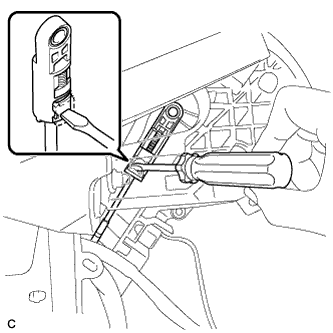
Pass the control cable from the cabin to the engine compartment.
-
Install the transmission control cable assembly with the 3 bolts.
- Torque:
- 5.0 N*m { 51 kgf*cm, 44 in.*lbf }
-
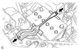
Install a new clip to the control cable bracket.
-
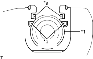
Text in Illustration *1 Control Cable *a Claw A *b Claw B Install the control cable to the control cable bracket.
Note
-
Make sure that the claws A on the clip are securely fit into the bracket holes.
-
Make sure that the cable is securely installed inside of the claws B of the clip.
-
-
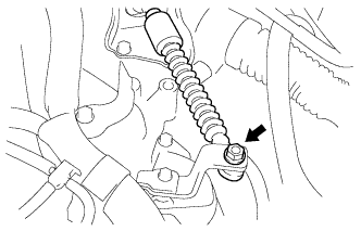
Connect the transmission control cable to the control shaft lever with the nut.
- Torque:
- 12 N*m { 122 kgf*cm, 9 ft.*lbf }
Note
Before connecting the transmission control cable assembly, check that the park/neutral position switch and the shift lever are in neutral.
-
-
INSTALL AIR CLEANER ASSEMBLY
-

Text in Illustration *a A side view *b Front of the vehicle *c 11 to 14 mm (0.433 to 0.551 in.) Install the air cleaner hose with the hose clamp.
Note
Install the air cleaner hose clamp so that the orientation is as shown in the illustration.
-

Text in Illustration *a Tab *b Hole Insert the tab of the air cleaner assembly to the hole of the vehicle body as shown in the illustration.
-
Install the air cleaner assembly with the 2 bolts.
- Torque:
- 5.5 N*m { 56 kgf*cm, 49 in.*lbf }
-

Text in Illustration *a Light blue paint mark Connect the vacuum hose to the 2 clamps of the air cleaner hose.
Note
Align the light blue paint mark of the vacuum hose with the clamp of the air cleaner hose.
-
Connect the vacuum hose.
-
Connect the ventilation hose to the cylinder head cover.
-
Connect the vacuum switching valve connector and install the vacuum hose to the 2 clamps.
-
Connect the No. 2 fuel vapor feed hose to the vacuum switching valve and clamp of the air cleaner hose.
-
Connect the mass air flow meter connector and install the wire harness clamp to the air cleaner assembly.
-
Connect the vacuum switching valve connector and install the wire harness clamp to the air cleaner assembly.
-
-
INSTALL INLET NO. 1 AIR CLEANER
-
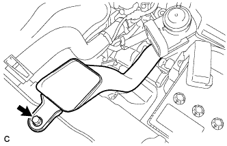
Install the No. 1 air cleaner inlet with the bolt.
- Torque:
- 8.0 N*m { 82 kgf*cm, 71 in.*lbf }
-
-
INSTALL INLET NO. 2 AIR CLEANER
-
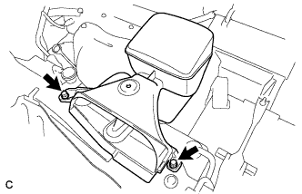
Install the No. 2 air cleaner inlet with the 2 bolts.
- Torque:
- 8.0 N*m { 82 kgf*cm, 71 in.*lbf }
-
-
INSTALL NO. 1 ENGINE COVER SUB-ASSEMBLY
-
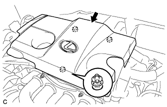
Fit the 3 retainers and install the No. 1 engine cover sub-assembly.
-
-
INSTALL BATTERY
-
Install the battery and battery tray.
-
Install the battery clamp with the bolt and nut.
- Torque:
- 5.4 N*m { 55 kgf*cm, 48 in.*lbf }
-
Connect the positive (+) cable to the positive (+) battery terminal.
- Torque:
- 6.4 N*m { 65 kgf*cm, 57 in.*lbf }
-
-
INSTALL INSTRUMENT PANEL REINFORCEMENT ASSEMBLY WITH AIR CONDITIONING UNIT ASSEMBLY
-
INSPECT SHIFT LEVER POSITION
-
When moving the shift lever from P to R with the engine switch on (IG) and the brake pedal depressed, make sure that the shift lever moves smoothly and correctly into position.
-
Start the engine and make sure that the vehicle moves forward when moving the shift lever from N to D and moves rearward when moving the shift lever to R.
If the operation cannot be performed as specified, inspect the park/neutral position switch assembly and check the shift lever assembly installation condition.
-
-
ADJUST SHIFT LEVER POSITION
-
Apply the parking brake and move the shift lever to N.
-
Remove the console box Click here.
-
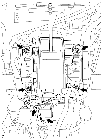
Disconnect the shift lock control ECU connector and transmission control switch wire connector.
-
Disconnect the 3 clamps.
-
Remove the 4 nuts and shift lever assembly.
-
Disconnect the end of the transmission control cable assembly from the shift lever assembly.
-
Turn the lock nut counterclockwise. While holding the lock nut, disconnect the transmission control cable from the shift lever retainer.
-
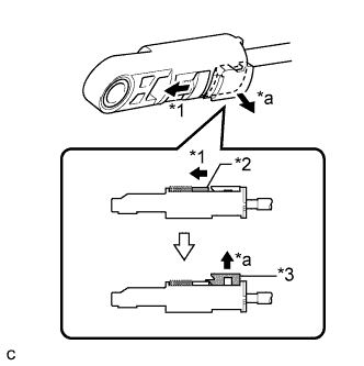
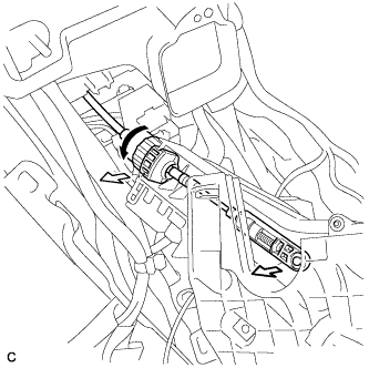
Text in Illustration *1 Slide *2 Slider *3 Lock Piece *a Pull Slide the slider of the transmission control cable in the direction indicated by the arrow and pull the lock piece outward.
-
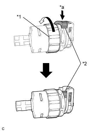
Text in Illustration *1 Lock Nut *2 Stopper *a Push in Turn the lock nut of the transmission control cable counterclockwise. While holding the lock nut, push in the stopper.
-
Connect the outer part of the transmission control cable to the shift lever retainer.
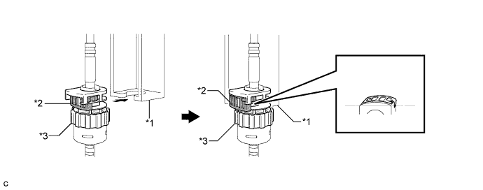
Text in Illustration *1 Shift Lever Retainer *2 Stopper *3 Lock Nut - - Note
The lock nut is fully seated against the shift lever retainer.
-
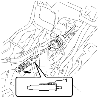
Text in Illustration *1 Lock Piece Install the transmission control cable end to the shift lever assembly.
Note
-
Check that the lock piece is pulled up.
-
Install the cable end all the way to the base of the pin.
-
-
Install the shift lever assembly with the 4 nuts.
- Torque:
- 12 N*m { 122 kgf*cm, 9 ft.*lbf }
-
Connect the 3 clamps to the shift lever assembly.
-
Connect the 2 connectors.
-
Push the lock piece into the adjuster case.
Note
-
Check that the park/neutral position switch and the shift lever are in neutral.
-
Securely push in the lock piece until the slider lock is engaged.
-
-
After adjusting the shift lever position, check the operation and function of the shift lever. If there is a problem, adjust the position again.
-
Install the console box Click here.
-