PARK / NEUTRAL POSITION SWITCH REMOVAL

-
PRECAUTION
Note
After turning the engine switch off, waiting time may be required before disconnecting the cable from the negative (-) battery terminal. Therefore, make sure to read the disconnecting the cable from the negative (-) battery terminal notices before proceeding with work Click here.
-
REMOVE WINDSHIELD WIPER MOTOR AND LINK ASSEMBLY
-
SEPARATE HOSE BRACKET (for LHD)
-
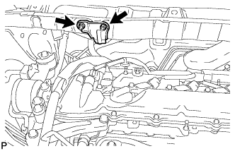
Remove the 2 nuts and separate the hose bracket from the outer cowl top panel sub-assembly.
-
-
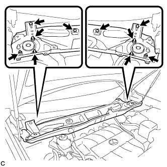
REMOVE OUTER COWL TOP PANEL SUB-ASSEMBLY (for LHD)
-
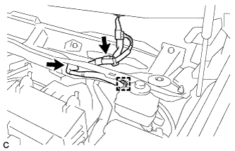
Disconnect the connector (w/ Windshield Deicer).
-
Disengage the grommet and clamp, and separate the wire harness.
-
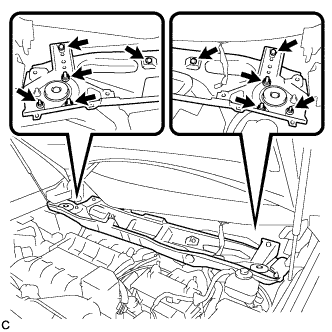
Remove the 6 nuts, 4 bolts and outer cowl top panel sub-assembly.
-
-
REMOVE OUTER COWL TOP PANEL SUB-ASSEMBLY (for RHD)
-
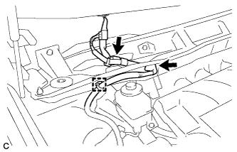
Disconnect the connector (w/ Windshield Deicer).
-
Disengage the grommet and clamp, and separate the wire harness.
-
Remove the 6 nuts, 4 bolts and outer cowl top panel sub-assembly.
-
-
REMOVE NO. 1 ENGINE COVER SUB-ASSEMBLY
-
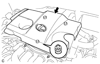
Lift the rear of the No. 1 engine cover sub-assembly to detach the cover from the 2 pins, and then lift the front of the No. 1 engine cover sub-assembly to detach the cover from the pin and remove the No. 1 engine cover sub-assembly.
Note
Attempting to disengage both front and rear clips at the same time may cause the No. 1 engine cover sub-assembly to break.
-
-
DISCONNECT CABLE FROM NEGATIVE BATTERY TERMINAL
Note
When disconnecting the cable, some systems need to be initialized after the cable is reconnected Click here.
-
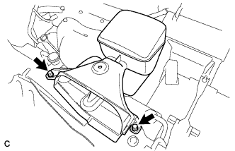
REMOVE BATTERY
-
Disconnect the positive (+) cable from the positive (+) battery terminal.
-
Loosen the nut, and remove the bolt from the battery clamp.
-
Remove the battery and battery tray.
-
-
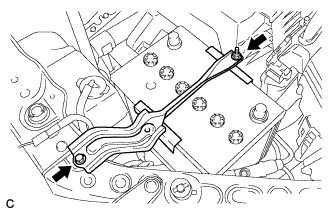
REMOVE INLET NO. 2 AIR CLEANER
-
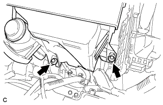
Remove the 2 bolts and No. 2 air cleaner inlet.
-
-
REMOVE INLET NO. 1 AIR CLEANER
-
Remove the bolt and No. 1 air cleaner inlet.
-
-
REMOVE AIR CLEANER ASSEMBLY
-
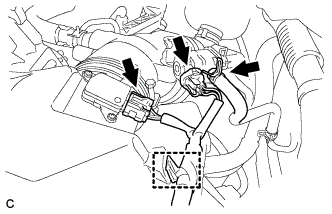
Disconnect the vacuum switching valve connector and fuel vapor feed hose.
-
Disconnect the mass air flow meter connector and separate the wire harness clamp from the air cleaner.
-
Disconnect the No. 2 fuel vapor feed hose from the vacuum switching valve and air cleaner hose.
-
Disconnect the vacuum switching valve connector and 2 wire harness clamps from the air cleaner.
-
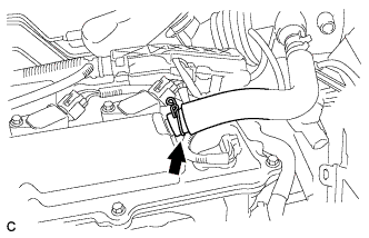
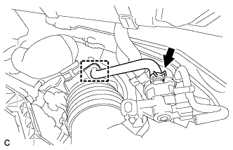
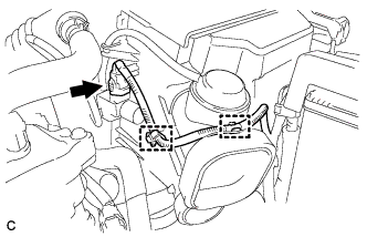
Disconnect the ventilation hose from the cylinder head cover.
-
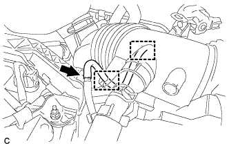
Disconnect the vacuum hose and separate it from the 2 hose clamps of the air cleaner hose.
-
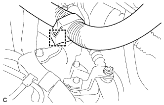
Loosen the bolt of the hose clamp and disconnect the air cleaner hose from the throttle body assembly.
-
Remove the 2 bolts and move the air cleaner assembly upward to disengage and remove it from the throttle body assembly.
-
-
SEPARATE TRANSMISSION CONTROL CABLE ASSEMBLY
-
Move the shift lever to N.
-
Disconnect the wire harness clamp.
-
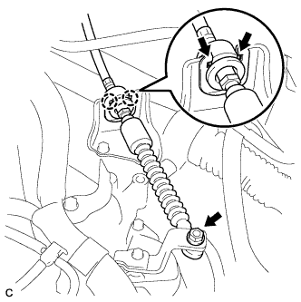
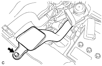
Remove the nut from the control shaft lever.
-
Using a screwdriver, disengage the 4 claws and disconnect the control cable with clip from the control cable bracket.
-
Remove the clip.
-
-
REMOVE PARK/NEUTRAL POSITION SWITCH ASSEMBLY
-
Disconnect the connector from the park/neutral position switch.
-
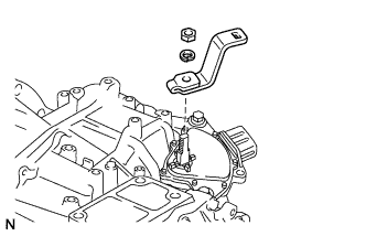
Remove the nut, washer and control shaft lever from the control shaft.
-
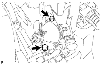
Remove the 2 bolts and park/neutral position switch from the control shaft.
Note
Before removing the park/neutral position switch, remove any dirt or rust on the installation portion of the control shaft. Be sure to remove the switch straight along the shaft while being careful not to deform the plate spring that supports the shaft. If the plate spring is deformed, the park/neutral position switch cannot be reinstalled correctly.
-