AUTOMATIC TRANSAXLE SYSTEM, Diagnostic DTC:P2759

| DTC Code | DTC Name |
|---|---|
| P2759 | Torque Converter Clutch Pressure Control Solenoid Control Circuit Electrical (Shift Solenoid Valve SLU) |
DESCRIPTION
The amount of current flow to the solenoid is controlled by the duty ratio* of the TCM output signal. The higher the duty ratio becomes, the higher the lock-up hydraulic pressure becomes during the lock-up operation.
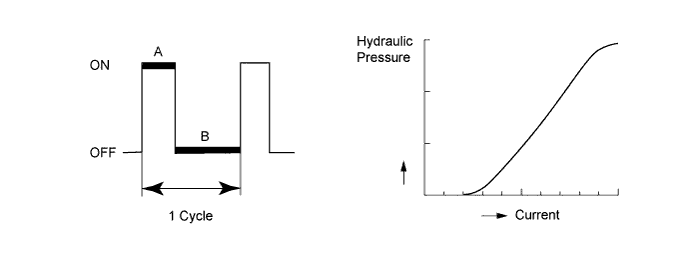
*: Duty Ratio
The duty ratio is the ratio of the electrical current on time (A) to the total of the electrical current on and off time (A + B).
Duty Ratio (%) = (A / (A + B)) x 100
| DTC No. | DTC Detection Condition
|
Trouble Area |
|---|---|---|
| P2759 |
|
|
MONITOR DESCRIPTION
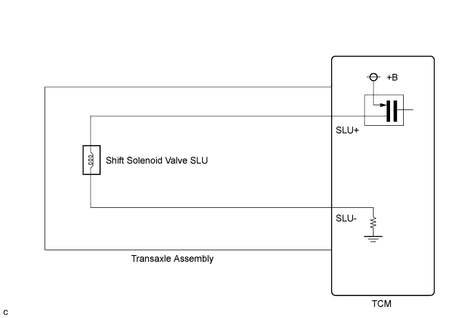
When an open or short in a shift solenoid valve (SLU) circuit is detected, the TCM determines there is a malfunction. The TCM will turn on the MIL and store this DTC.
WIRING DIAGRAM
INSPECTION PROCEDURE
PROCEDURE
-
INSPECT TRANSMISSION WIRE (SLU)
-
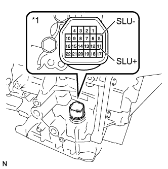
Text in Illustration *1 Component without harness connected
(Transmission Wire)
Remove the TCM from the transaxle.
-
Measure the resistance according to the value(s) in the table below.
Standard Resistance Tester Connection Condition Specified Condition 11 (SLU+) - 5 (SLU-) 20°C (68°F) 5.0 to 5.6 Ω 11 (SLU+) - Body ground or other terminals Always 10 kΩ or higher 5 (SLU-) - Body ground or other terminals Always 10 kΩ or higher 11 (SLU+) - All other terminals except 5 (SLU-) Always 10 kΩ or higher 5 (SLU-) - All other terminals except 11 (SLU+) Always 10 kΩ or higher Result Result Proceed to OK B NG A
B 
REPLACE TCM Click here
A 
-
-
INSPECT SHIFT SOLENOID VALVE SLU
-
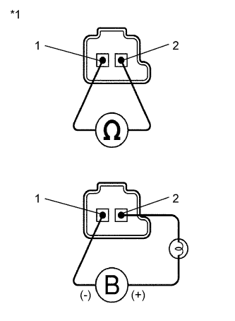
Text in Illustration *1 Shift Solenoid Valve SLU Remove shift solenoid valve SLU.
-
Measure the resistance according to the value(s) in the table below.
Standard Resistance Tester Connection Condition Specified Condition 1 - 2 20°C (68°F) 5.0 to 5.6 Ω -
Connect a battery positive (+) lead with a 21 W bulb to terminal 2 and a negative (-) lead to terminal 1 of the solenoid valve connector. Then check that the valve moves and makes an operating sound.
OK Valve moves and makes an operating sound.
NG
REPLACE SHIFT SOLENOID VALVE SLU Click here
OK 
REPLACE TRANSMISSION WIRE Click here
-