AUTOMATIC TRANSAXLE ASSEMBLY REMOVAL

Note
If automatic transmission parts are replaced, refer to Parts Replacement Compensation Table to determine if any additional operations are necessary Click here.
-
REMOVE ENGINE ASSEMBLY WITH TRANSAXLE
Tech Tips
See the steps from "Precaution" through "Remove Engine Assembly with Transaxle" Click here.
-
REMOVE STARTER ASSEMBLY
-
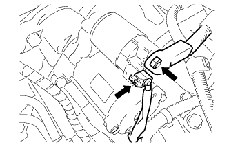
Disconnect the starter connector.
-
Turn back the terminal cap, remove the nut and disconnect the starter wire.
-
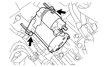
Remove the 2 bolts and starter.
-
-
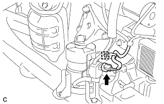
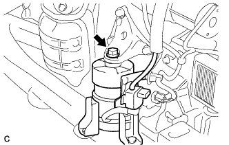
REMOVE RADIATOR PIPE CLAMP
-
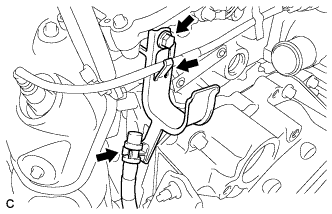
Separate the breather plug hose and sensor wire from the radiator pipe clamp.
-
Remove the bolt and radiator pipe clamp.
-
-
REMOVE FRONT NO. 1 STABILIZER BRACKET LH
-
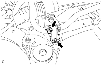
Remove the 2 bolts and the front No. 1 stabilizer bracket LH from the front frame assembly.
-
-
REMOVE FRONT NO. 1 STABILIZER BRACKET RH
Tech Tips
Perform the same procedure as for the LH side.
-
REMOVE FRONT STABILIZER BAR WITH FRONT STABILIZER LINK ASSEMBLY
-
Remove the front stabilizer bar with front stabilizer link assembly.
-
-
REMOVE STEERING LINK ASSEMBLY
-
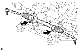
Remove the 2 bolts, 2 nuts and steering link assembly.
Note
Because the nut has its own stopper, do not turn the nut. Loosen the bolt with the nut secured.
-
-
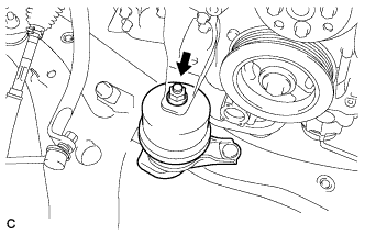
REMOVE FRONT FRAME ASSEMBLY
-
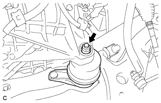
Remove the nut and separate the engine mounting insulator LH.
-
Disconnect the wire clamp and connector.
-
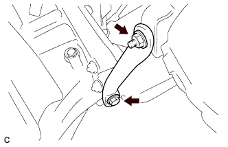
Remove the bolt and separate the front engine mounting insulator.
-
Remove the nut and separate the engine mounting insulator RH.
-
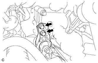
Remove the 2 bolts and separate the rear engine mounting insulator assembly.
Note
Do not remove the rear engine mounting insulator assembly through bolts. Doing so makes it difficult to install the rear engine mounting insulator assembly.
-
Remove the front frame assembly.
-
-
REMOVE MANIFOLD STAY
-
Remove the bolt, nut and manifold stay.
-
-
REMOVE TCM
-
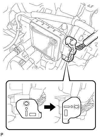
Turn the lock lever and disconnect the connector from the TCM.
-
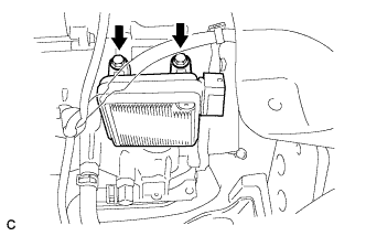
Remove the 2 bolts and TCM from the transaxle.
-
-
SEPARATE WIRE HARNESS
-
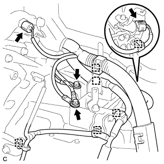
Remove the 2 bolts and disconnect the 2 wire harnesses.
-
Separate the 2 connectors and 6 wire harness clamps.
-
-
REMOVE TRANSFER STIFFENER PLATE RH
-
Remove the 4 bolts and transfer stiffener plate RH.
-
-
REMOVE AUTOMATIC TRANSAXLE ASSEMBLY
-
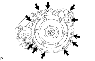
Remove the 11 bolts and transaxle.
Note
To prevent damage to the knock pins, do not pry between the transaxle and engine.
-
-
REMOVE TRANSFER ASSEMBLY
-
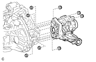
Remove the 8 nuts.
-
Using a plastic hammer, remove the transfer assembly from the transaxle assembly.
Note
-
Remove the transfer assembly from the transaxle assembly without tilting it.
-
During removal, do not hold the transfer assembly by the oil seals on either side of the assembly.
-
-
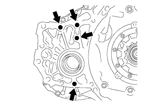
Remove the 4 transfer and transaxle setting stud bolts.
-
-
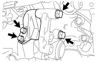
REMOVE FRONT ENGINE MOUNTING BRACKET
-
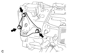
Remove the 3 bolts and front engine mounting bracket from the automatic transaxle assembly.
-
-
REMOVE WIRE HARNESS CLAMP BRACKET
-
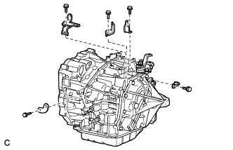
Remove the 5 bolts and 5 clamp brackets.
-
-
REMOVE NO. 1 TRANSMISSION CONTROL CABLE BRACKET
-
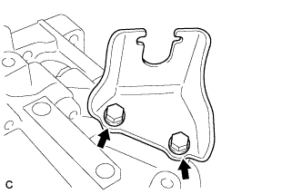
Remove the 2 bolts and No. 1 transmission control cable bracket from the automatic transaxle assembly.
-
-
REMOVE SPEEDOMETER DRIVEN HOLE (ATM) COVER SUB-ASSEMBLY
-
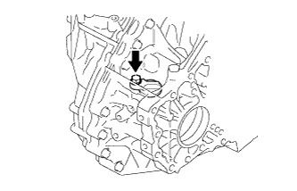
Remove the bolt and speedometer driven hole (ATM) cover sub-assembly from the automatic transaxle assembly.
-
Remove the O-ring from the speedometer driven hole (ATM) cover sub-assembly.
-
-
REMOVE TORQUE CONVERTER ASSEMBLY
-
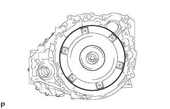
Remove the torque converter assembly from the automatic transaxle assembly.
-
-
INSPECT TORQUE CONVERTER ASSEMBLY
-
Inspect the one-way clutch.
-
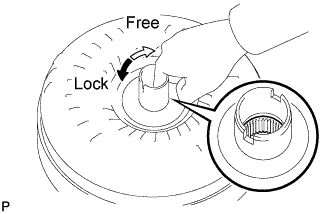
Press on the spline of the stator with a finger and rotate it. Check that it rotates smoothly when turned clockwise and locks when turned counterclockwise.
If necessary, clean the torque converter assembly and recheck the one-way clutch.
Replace the torque converter assembly if the one-way clutch still fails the check.
-
-
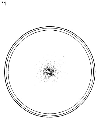
Text in Illustration *1 Sample showing maximum allowable amount of powder in ATF Determine the condition of the torque converter assembly.
-
If the inspection result of the torque converter assembly satisfies the following conditions, replace the torque converter assembly.
Malfunction A metallic sound is emitted from the torque converter assembly during the stall test or when the shift lever is moved to N. The one-way clutch is free or locks in both directions.
The amount of powder in the ATF is greater than the sample shown in the illustration (see the sample).
Tech Tips
The sample shows approximately 0.25 liters (0.26 US qts, 0.22 Imp. qts) of ATF that is taken out from the removed torque converter assembly.
-
-
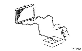
Replace the ATF in the torque converter assembly.
-
If the ATF is discolored and/or has foul odor, stir the ATF in the torque converter assembly and drain it.
-
-
Clean and check the oil cooler and oil pipe line.
-
If the torque converter assembly is inspected or the ATF is replaced, clean the oil cooler and oil pipe line.
Tech Tips
-
Apply compressed air of 196 kPa (2.0 kgf/ cm2, 28 psi) into the inlet hose.
-
If a large amount of powder is found in the ATF, add new ATF using a bucket pump and clean the oil cooler and oil pipe line again.
-
-
If the ATF is cloudy, inspect the oil cooler (radiator).
-
-
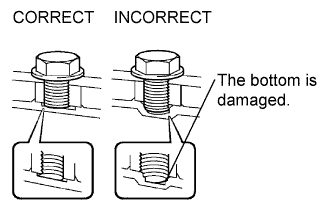
Prevent deformation of the torque converter assembly and damage to the oil pump gear.
-
When there is any damage due to the end of the bolt for the torque converter assembly and to the bottom of the bolt hole, replace the bolt and the torque converter assembly.
-
All of the bolts should be the same length.
-
Bolts with washers must be used.
-
-