TRANSMISSION CONTROL CABLE INSTALLATION

-
INSTALL TRANSMISSION CONTROL CABLE ASSEMBLY
Note
Before installing the transmission control cable assembly, check that the park/neutral position switch and the shift lever are in neutral.
-
Pass the control cable from the cabin to the engine compartment.
-
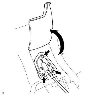
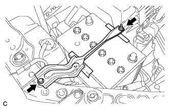
Install the transmission control cable assembly with the 3 bolts.
- Torque:
- 5.0 N*m { 51 kgf*cm, 44 in.*lbf }
-
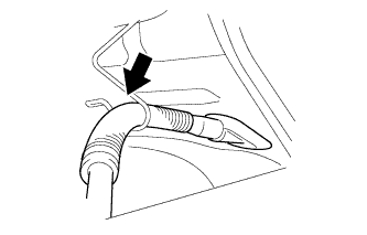
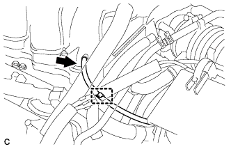
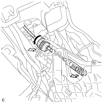
Connect the transmission control cable to the clamp.
-
Install a new clip to the control cable bracket.
-
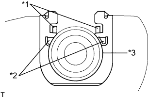
Text in Illustration *1 Claw A *2 Claw B *3 Control Cable Install the control cable to the control cable bracket.
Note
-
Make sure that the claws A on the clip are securely fit into the bracket holes.
-
Make sure that the cable is securely installed inside of the claws B of the clip.
-
-
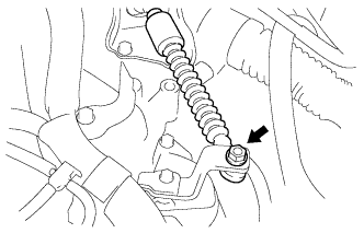
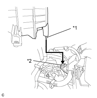
Connect the transmission control cable to the control shaft lever with the nut.
- Torque:
- 12 N*m { 122 kgf*cm, 9 ft.*lbf }
Note
Before connecting the transmission control cable assembly, check that the park/neutral position switch and the shift lever are in neutral.
-
-
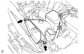
INSTALL AIR CLEANER ASSEMBLY
-
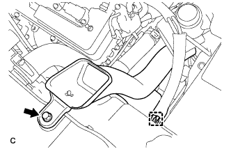
Text in Illustration *1 Tab *2 Hole Insert the tab of the air cleaner assembly to the hole of the vehicle body as shown in the illustration.
-
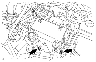
Install the air cleaner assembly with the 2 bolts.
- Torque:
- 5.5 N*m { 56 kgf*cm, 49 in.*lbf }
-
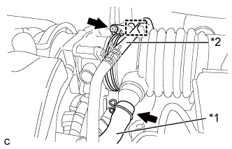
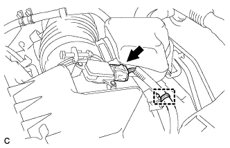
Text in Illustration *1 Ventilation Hose *2 Fuel Vapor Feed Hose Connect the air cleaner hose to the throttle body with the hose clamp.
-
Connect the ventilation hose and the fuel vapor feed hose.
-
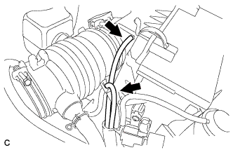
Connect the 2 vacuum hoses.
-
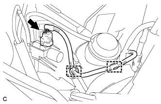
Connect the 2 wire harness clamps and vacuum switching valve connector.
-
Connect the vacuum hose to the intake air surge tank assembly.
-
Install the hose to the hose clamp.
-
Connect the mass air flow meter connector and wire harness clamp.
-
-
INSTALL INLET NO. 1 AIR CLEANER
-
Install the No. 1 air cleaner inlet with the bolt.
- Torque:
- 8.0 N*m { 82 kgf*cm, 71 in.*lbf }
-
Connect the vacuum hose clamp to the No. 1 air cleaner inlet.
-
-
INSTALL INLET NO. 2 AIR CLEANER
-
Install the No. 2 air cleaner inlet with the 2 bolts.
- Torque:
- 8.0 N*m { 82 kgf*cm, 71 in.*lbf }
-
Connect the 2 vacuum hose clamps to the No. 2 air cleaner inlet.
-
-
INSTALL V-BANK COVER SUB-ASSEMBLY
-
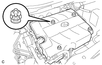
Fit the 4 retainers and install the V-bank cover sub-assembly.
-
-
INSTALL BATTERY
-
Install the battery and battery tray.
-
Install the battery clamp with the bolt and nut.
- Torque:
- 5.4 N*m { 55 kgf*cm, 48 in.*lbf }
-
Connect the positive (+) cable to the positive (+) battery terminal.
- Torque:
- 6.4 N*m { 65 kgf*cm, 57 in.*lbf }
-
-
INSTALL INSTRUMENT PANEL REINFORCEMENT ASSEMBLY WITH AIR CONDITIONING UNIT ASSEMBLY
Tech Tips
See the steps from "Install Instrument Panel Reinforcement Assembly with Air Conditioning Unit Assembly" through "Inspect SRS Warning Light" Click here.
-
INSPECT SHIFT LEVER POSITION
-
When moving the shift lever from P to R with the engine switch on (IG) and the brake pedal depressed, make sure that the shift lever moves smoothly and correctly into position.
-
Start the engine and make sure that the vehicle moves forward when moving the shift lever from N to D and moves rearward when moving the shift lever to R.
If the operation cannot be performed as specified, inspect the park/neutral position switch assembly and check the shift lever assembly installation condition.
-
-
ADJUST SHIFT LEVER POSITION
-
Apply the parking brake and move the shift lever to N.
-
Remove the console box Click here.
-
Disconnect the shift lock control ECU connector and transmission control switch wire connector.
-
Disconnect the 3 clamps.
-
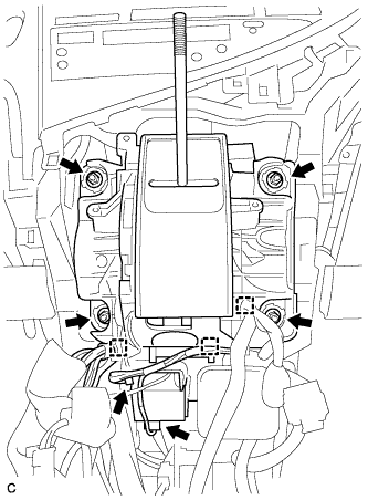
Remove the 4 nuts and shift lever assembly.
-
Disconnect the end of the transmission control cable assembly from the shift lever assembly.
-
Turn the lock nut counterclockwise. While holding the lock nut, disconnect the transmission control cable from the shift lever retainer.
-
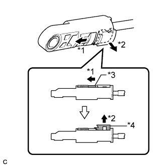
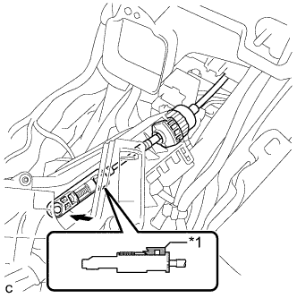
Text in Illustration *1 Slide *2 Pull *3 Slider *4 Lock Piece Slide the slider of the transmission control cable in the direction indicated by the arrow and pull the lock piece outward.
-
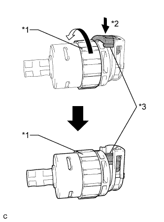
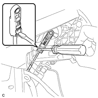
Text in Illustration *1 Lock Nut *2 Push in *3 Stopper Turn the lock nut of the transmission control cable counterclockwise. While holding the lock nut, push in the stopper.
-
Connect the outer part of the transmission control cable to the shift lever retainer.
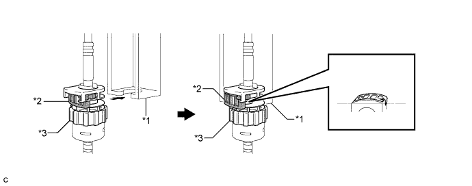
Text in Illustration *1 Shift Lever Retainer *2 Stopper *3 Lock Nut - - Note
The lock nut is fully seated against the shift lever retainer.
-
Text in Illustration *1 Lock Piece Install the transmission control cable end to the shift lever assembly.
Note
-
Check that the lock piece is pulled up.
-
Install the cable end all the way to the base of the pin.
-
-
Install the shift lever assembly with the 4 nuts.
- Torque:
- 12 N*m { 122 kgf*cm, 9 ft.*lbf }
-
Connect the 3 clamps to the shift lever assembly.
-
Connect the 2 connectors.
-
Push the lock piece into the adjuster case.
Note
-
Check that the park/neutral position switch and the shift lever are in neutral.
-
Securely push in the lock piece until the slider lock is engaged.
-
-
After adjusting the shift lever position, check the operation and function of the shift lever. If there is a problem, adjust the position again.
-
Install the console box Click here.
-