AUTOMATIC TRANSAXLE SYSTEM, Diagnostic DTC:P0617

| DTC Code | DTC Name |
|---|---|
| P0617 | Starter Relay Circuit High |
DESCRIPTION
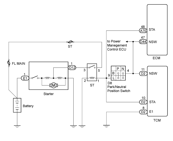
While the engine is being cranked, battery voltage is applied to terminal STA of the TCM.
If the TCM detects the starter control (STA) signal while the vehicle is being driven, it determines that there is a malfunction in the STA circuit. The TCM then illuminates the MIL and sets the DTC.
This monitor runs when the vehicle is driven at 20 km/h (12.4 mph) for over 20 seconds.
| DTC No. | DTC Detection Condition
|
Trouble Area |
|---|---|---|
| P0617 |
|
|
WIRING DIAGRAM
INSPECTION PROCEDURE
Tech Tips
-
The following troubleshooting flowchart is based on the premise that the engine is cranked normally. If the engine does not crank, proceed to the problem symptoms table Click here.
PROCEDURE
-
READ VALUE USING INTELLIGENT TESTER (STARTER SIGNAL)
-
Connect the intelligent tester to the DLC3.
-
Turn the engine switch on (IG).
-
Turn the intelligent tester on.
-
Enter the following menus: Powertrain / ECT / Data List.
Tester Display Measurement Item/Range Normal Condition Diagnostic Note Starter Signal Starter signal/
Open or Close
Open: Cranking
Close: Engine switch on (IG)
- -
Read the value displayed on the intelligent tester.
-
Crank the engine.
-
Read the value displayed on the intelligent tester.
OK Tester Display Condition Standard Starter Signal Engine switch on (IG) Close Starter Signal Engine is cranking Open Result Result Proceed to NG A OK B
B 
CHECK TCM (STA VOLTAGE) Click here
A 
-
-
INSPECT PARK/NEUTRAL POSITION SWITCH ASSEMBLY
-
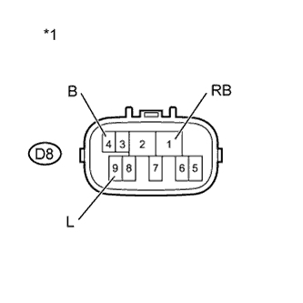
Text in Illustration *1 Component without harness connected
(Park/Neutral Position Switch Assembly)
Disconnect the park/neutral position switch connector.
-
Measure the resistance according to the value(s) in the table below when the shift lever is moved to each position.
Standard Resistance Tester Connection Shift Lever Position Specified Condition 4 (B) - 9 (L) P Below 1 Ω N Below 1 Ω Except P and N 10 kΩ or higher 1 (RB) - 9 (L) P 10 kΩ or higher R 10 kΩ or higher N 10 kΩ or higher D 10 kΩ or higher
NG 
REPLACE PARK/NEUTRAL POSITION SWITCH ASSEMBLY Click here
OK
-
-
CHECK TCM (STA VOLTAGE)
-
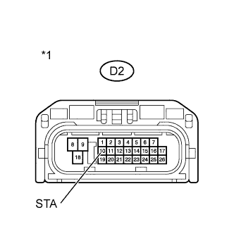
Text in Illustration *1 Front view of wire harness connector
(to TCM)
Connect the park/neutral position switch connector.
-
Disconnect the TCM connector.
-
Measure the voltage according to the value(s) in the table below.
Standard Voltage Tester Connection Condition Specified Condition D2-10 (STA) - Body ground Engine switch on (IG) and shift lever in P or N Below 2 V Engine switch on (IG) and shift lever not in P or N Below 1 V
NG
CHECK HARNESS AND CONNECTOR (TCM - PARK/NEUTRAL POSITION SWITCH) Click here
OK 
REPLACE TCM Click here
-
-
CHECK HARNESS AND CONNECTOR (TCM - PARK/NEUTRAL POSITION SWITCH)
-
Text in Illustration *1 Front view of wire harness connector
(to TCM)
Disconnect the TCM connector.
-
Remove the ST relay from the engine room relay block.
-
Disconnect the park/neutral position switch connector.
-
Measure the voltage according to the value(s) in the table below.
Standard Voltage Tester Connection Condition Specified Condition D2-10 (STA) - Body ground Engine switch on (IG) Below 1 V
NG
REPAIR OR REPLACE HARNESS OR CONNECTOR
OK
CHECK STARTER SIGNAL CIRCUIT Click here
-