VALVE BODY ASSEMBLY INSTALLATION

-
INSTALL MANUAL VALVE
-
Coat the manual valve with ATF and install it to the valve body.
-
-
INSTALL TRANSMISSION VALVE BODY ASSEMBLY
-
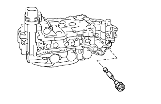
Coat the O-ring of the transmission wire with ATF.
-
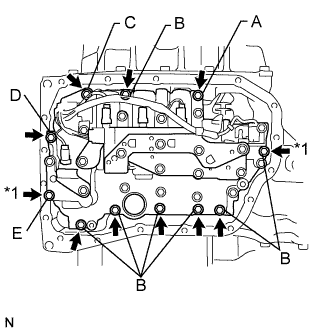
Confirm that the manual valve lever is positioned as shown in the illustration and install the valve body assembly to the transaxle case with the 11 bolts.
- Torque:
- 11 N*m { 112 kgf*cm, 8 ft.*lbf }
Bolt length Bolt A 25 mm (0.984 in.) Bolt B 30 mm (1.18 in.) Bolt C 35 mm (1.38 in.) Bolt D 45 mm (1.77 in.) Bolt E 55 mm (2.17 in.) Note
-
When installing the transmission valve body assembly, be careful not to allow the transmission revolution sensor and transaxle case to interfere with each other.
-
Be sure to insert the pin of the manual valve lever into the groove on the end of the manual valve.
-
First, temporarily tighten the bolts marked *1 in the illustration because they are positioning bolts.
-
-
INSTALL VALVE BODY OIL STRAINER ASSEMBLY
-
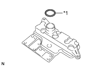
Text in Illustration *1 O-ring Coat a new O-ring with ATF and install it to the oil strainer.
Note
Ensure that the O-ring is not twisted or pinched.
-
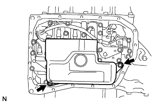
Install the oil strainer to the valve body with the 2 bolts.
- Torque:
- 11 N*m { 112 kgf*cm, 8 ft.*lbf }
-
-
INSTALL AUTOMATIC TRANSAXLE OIL PAN SUB-ASSEMBLY
-
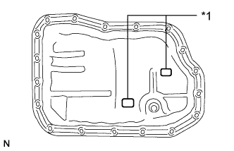
Text in Illustration *1 Magnet Install the 2 magnets to the oil pan.
-
Install a new gasket to the oil pan.
-
Apply adhesive to the 18 bolts.
Adhesive Toyota Genuine Adhesive 1344, Three Bond 1344 or equivalent -
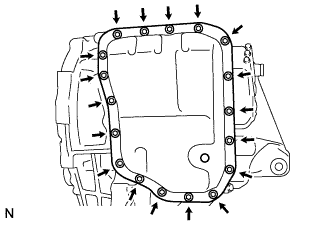
Install the oil pan to the automatic transaxle with the 18 bolts.
- Torque:
- 7.0 N*m { 71 kgf*cm, 62 in.*lbf }
Note
-
In order to ensure proper sealing of the transmission oil pan bolts, apply adhesive to the bolts and install them within 10 minutes of adhesive application.
-
Completely remove any oil or grease from the contact surface of the transaxle case and oil pan sub-assembly with the gasket before installation.
-
-
INSTALL TORQUE CONVERTER ASSEMBLY
-
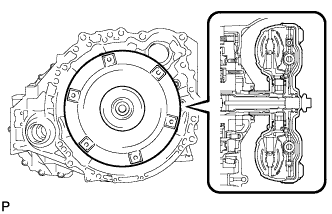
Engage the splines of the input shaft and turbine runner.
-
Engage the splines of the stator shaft and the stator while turning the torque converter assembly.
Tech Tips
If the stator shaft splines are difficult to engage with the stator splines, move the torque converter assembly back approximately 10 mm (0.393 in.) and engage the splines while rotating the torque converter assembly.
-
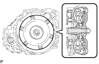
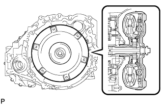
Turn the torque converter assembly to engage the key of the oil pump drive gear into the slot on the torque converter assembly.
-
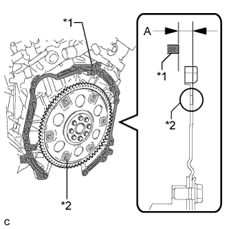
Using a vernier caliper and a straightedge, measure dimension "A" between the transaxle fitting surface of the engine*1 and the torque converter assembly fitting surface of the drive plate*2. (#)
Note
Make sure to deduct the thickness of the straightedge.
-
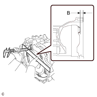
Using a vernier caliper and a straightedge, measure dimension "B" shown in the illustration and check that "B" is greater than "A" (measured in step (#)).
Standard A + 1 mm (0.0394 in.) or more Note
-
Make sure to deduct the thickness of the straightedge.
-
If the transaxle is installed to the engine with the torque converter assembly not sufficiently inserted, the torque converter assembly may be damaged.
Tech Tips
If a U660F is used with a 2GR-FE, the standard installation depth is 14 mm (0.551 in.) or more.
-
-
-
INSTALL TRANSFER ASSEMBLY
-
Install the 4 new transfer and transaxle setting stud bolts to the transaxle case positions shown in the illustration.
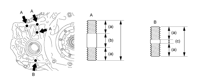
Stud bolt length a 22 mm (0.866 in.) b 25 mm (0.984 in.) c 5 mm (0.197 in.) - Torque:
- 39 N*m { 400 kgf*cm, 29 ft.*lbf }
Note
Install the sealed side of the stud bolt to the transaxle assembly.
-
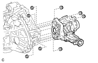
Install the transfer assembly to the transaxle assembly with the 8 nuts.
- Torque:
- 69 N*m { 700 kgf*cm, 51 ft.*lbf }
Note
-
Install the transfer assembly to the transaxle assembly horizontally.
-
Do not touch the transfer assembly oil seals during installation.
-
-
INSTALL AUTOMATIC TRANSAXLE ASSEMBLY
Tech Tips
See the steps from "Install Automatic Transaxle Assembly" through "Check Automatic Transaxle System" Click here.