VALVE BODY ASSEMBLY INSPECTION

-
INSPECT SHIFT SOLENOID VALVE SL
-
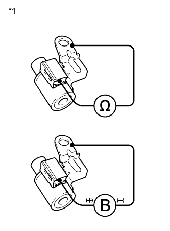
Text in Illustration *1 Shift Solenoid Valve SL Measure the resistance according to the value(s) in the table below.
Standard Resistance Tester Connection Condition Specified Condition Solenoid Connector (SL) - Solenoid Body (SL) 20°C (68°F) 11 to 15 Ω If the value is not as specified, replace the shift solenoid valve.
-
Connect a positive (+) lead from the battery to the terminal of the solenoid connector, and a negative (-) lead to the solenoid body, and check the operation of the valve.
Note
When using battery voltage during the inspection, do not bring the positive (+) and negative (-) tester probes too close to each other as a short circuit may occur.
OK The valve moves and makes an operating sound. If the operation cannot be done as specified, replace the shift solenoid valve.
-
-
INSPECT SHIFT SOLENOID VALVE SLT
-
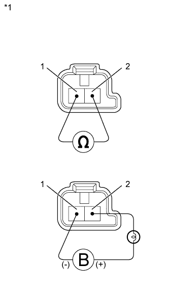
Text in Illustration *1 Component without harness connected
(Shift Solenoid Valve SLT)
Measure the resistance according to the value(s) in the table below.
Standard Resistance Tester Connection Condition Specified Condition 1 - 2 20°C (68°F) 5.0 to 5.6 Ω If the value is not as specified, replace the shift solenoid valve.
-
Connect a positive (+) lead from the battery with a 21 W bulb to terminal 2 and a negative (-) lead to terminal 1 of the solenoid valve connector, and check the operation of the valve.
Note
When using battery voltage during the inspection, do not bring the positive (+) and negative (-) tester probes too close to each other as a short circuit may occur.
OK The valve moves and makes an operating sound. If the operation cannot be done as specified, replace the shift solenoid valve.
-
-
INSPECT SHIFT SOLENOID VALVE SLU
-
Text in Illustration *1 Component without harness connected
(Shift Solenoid Valve SLU)
Measure the resistance according to the value(s) in the table below.
Standard Resistance Tester Connection Condition Specified Condition 1 - 2 20°C (68°F) 5.0 to 5.6 Ω If the value is not as specified, replace the shift solenoid valve.
-
Connect a positive (+) lead from the battery with a 21 W bulb to terminal 2 and a negative (-) lead to terminal 1 of the solenoid valve connector, and check the operation of the valve.
Note
When using battery voltage during the inspection, do not bring the positive (+) and negative (-) tester probes too close to each other as a short circuit may occur.
OK The valve moves and makes an operating sound. If the operation cannot be done as specified, replace the shift solenoid valve.
-
-
INSPECT SHIFT SOLENOID VALVE SL1
-
Text in Illustration *1 Component without harness connected
(Shift Solenoid Valve SL1)
Measure the resistance according to the value(s) in the table below.
Standard Resistance Tester Connection Condition Specified Condition 1 - 2 20°C (68°F) 5.0 to 5.6 Ω If the value is not as specified, replace the shift solenoid valve.
-
Connect a positive (+) lead from the battery with a 21 W bulb to terminal 2 and a negative (-) lead to terminal 1 of the solenoid valve connector, and check the operation of the valve.
Note
When using battery voltage during the inspection, do not bring the positive (+) and negative (-) tester probes too close to each other as a short circuit may occur.
OK The valve moves and makes an operating sound. If the operation cannot be done as specified, replace the shift solenoid valve.
-
-
INSPECT SHIFT SOLENOID VALVE SL2
-
Text in Illustration *1 Component without harness connected
(Shift Solenoid Valve SL2)
Measure the resistance according to the value(s) in the table below.
Standard Resistance Tester Connection Condition Specified Condition 1 - 2 20°C (68°F) 5.0 to 5.6 Ω If the value is not as specified, replace the shift solenoid valve.
-
Connect a positive (+) lead from the battery with a 21 W bulb to terminal 2 and a negative (-) lead to terminal 1 of the solenoid valve connector, and check the operation of the valve.
Note
When using battery voltage during the inspection, do not bring the positive (+) and negative (-) tester probes too close to each other as a short circuit may occur.
OK The valve moves and makes an operating sound. If the operation cannot be done as specified, replace the shift solenoid valve.
-
-
INSPECT SHIFT SOLENOID VALVE SL3
-
Text in Illustration *1 Component without harness connected
(Shift Solenoid Valve SL3)
Measure the resistance according to the value(s) in the table below.
Standard Resistance Tester Connection Condition Specified Condition 1 - 2 20°C (68°F) 5.0 to 5.6 Ω If the value is not as specified, replace the shift solenoid valve.
-
Connect a positive (+) lead from the battery with a 21 W bulb to terminal 2 and a negative (-) lead to terminal 1 of the solenoid valve connector, and check the operation of the valve.
Note
When using battery voltage during the inspection, do not bring the positive (+) and negative (-) tester probes too close to each other as a short circuit may occur.
OK The valve moves and makes an operating sound. If the operation cannot be done as specified, replace the shift solenoid valve.
-
-
INSPECT SHIFT SOLENOID VALVE SL4
-
Text in Illustration *1 Component without harness connected
(Shift Solenoid Valve SL4)
Measure the resistance according to the value(s) in the table below.
Standard Resistance Tester Connection Condition Specified Condition 1 - 2 20°C (68°F) 5.0 to 5.6 Ω If the value is not as specified, replace the shift solenoid valve.
-
Connect a positive (+) lead from the battery with a 21 W bulb to terminal 2 and a negative (-) lead to terminal 1 of the solenoid valve connector, and check the operation of the valve.
Note
When using battery voltage during the inspection, do not bring the positive (+) and negative (-) tester probes too close to each other as a short circuit may occur.
OK The valve moves and makes an operating sound. If the operation cannot be done as specified, replace the shift solenoid valve.
-