AUTOMATIC TRANSAXLE SYSTEM Shift Paddle Switch Circuit
DESCRIPTION
When moving the shift lever into the S position using the transmission control switch, it is possible to switch the shift range position between "1" (first range) and "6" (sixth range).
Shifting up "+" once raises one shift range position, and shifting down "-" lowers one shift range position.
When the shift lever is in D, operating the shift paddle switch will cause the transmission to enter fixed range mode which restricts the highest gear. By operating the shift paddle switches "+" (UP) or "-" (DOWN), the shift range can be changed.
When the vehicle is being operated in D position (fixed range mode), if the vehicle is stopped or the accelerator pedal is kept steady for a certain period of time with the transmission in the same gear, the vehicle will change back automatically to normal D position operation.
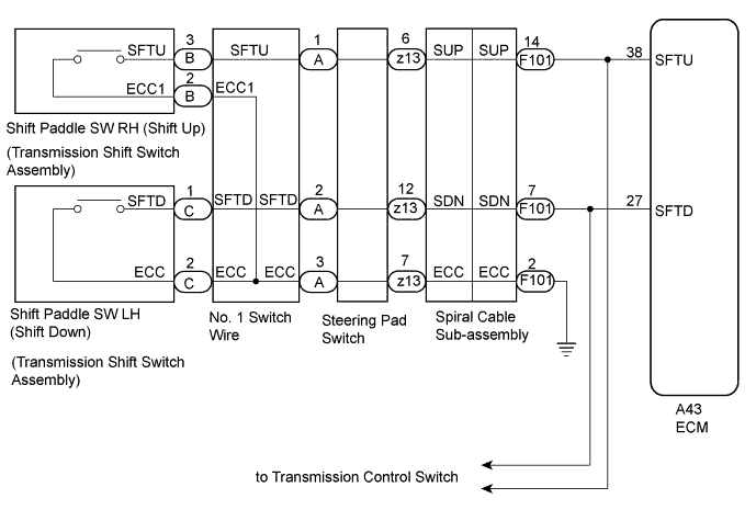
WIRING DIAGRAM
INSPECTION PROCEDURE
PROCEDURE
-
READ VALUE USING INTELLIGENT TESTER (SPORT SHIFT SWITCH STATUS)
-
Connect the intelligent tester to the DLC3.
-
Turn the engine switch on (IG).
-
Turn the intelligent tester on.
-
Enter the following menus: Powertrain / ECT / Data List.
-
According to the display on the intelligent tester, read the Data List.
Tester Display Measurement Item/Range Normal Condition Diagnostic Note Sports Shift Up SW Sport shift up switch status/
ON or OFF
-
ON: Continuously pull to "+" (up-shift)
-
OFF: Release "+" (up-shift)
- Sports Shift Down SW Sport shift down switch status/
ON or OFF
-
ON: Continuously pull to "-" (down-shift)
-
OFF: Release "-" (down-shift)
- Result Result Proceed to Data display is not within Normal Condition range A Data display is within Normal Condition range B -
B 
CHECK FOR INTERMITTENT PROBLEMS Click here
A 
-
-
CHECK HARNESS AND CONNECTOR (SHIFT PADDLE SWITCH CIRCUIT)
-
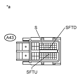
Text in Illustration *a Front view of wire harness connector
(to ECM)
Disconnect the ECM connector.
-
Turn the engine switch off.
-
Measure the resistance according to the value(s) in the table below.
Standard Resistance Tester Connection Switch Condition Specified Condition A43-27 (SFTD) - Body ground or other terminals Pull "-" continuously
(Down-shift)
Below 1 Ω Release 10 kΩ or higher A43-38 (SFTU) - Body ground or other terminals Pull "+" continuously
(Up-shift)
Below 1 Ω Release 10 kΩ or higher
NG 
CHECK HARNESS AND CONNECTOR (SPIRAL CABLE - BODY GROUND) Click here
OK 
PROCEED TO NEXT SUSPECTED AREA SHOWN IN PROBLEM SYMPTOMS TABLE Click here
-
-
CHECK HARNESS AND CONNECTOR (SPIRAL CABLE - BODY GROUND)
-
Disconnect the negative (-) terminal cable from the battery.
-
Wait for at least 90 seconds.
-
Remove the steering wheel assembly.
-
Remove the steering column cover.
-
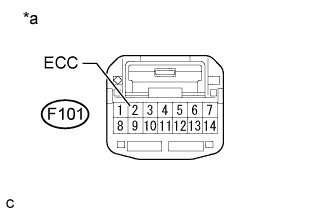
Text in Illustration *a Front view of wire harness connector
(to Spiral Cable Sub-assembly)
Disconnect the spiral cable connector.
-
Measure the resistance according to the value(s) in the table below.
Standard Resistance Tester Connection Condition Specified Condition F101-2 (ECC) - Body ground Always Below 1 Ω
NG
REPAIR OR REPLACE HARNESS OR CONNECTOR
OK
-
-
CHECK HARNESS AND CONNECTOR (SPIRAL CABLE - ECM)
-
Disconnect the ECM connector.
-
Measure the resistance according to the value(s) in the table below.
Standard Resistance Tester Connection Switch Condition Specified Condition A43-27 (SFTD) - F101-7 (SDN) Always Below 1 Ω A43-27 (SFTD) or F101-7 (SDN) - Body ground Always 10 kΩ or higher A43-38 (SFTU) - F101-14 (SUP) Always Below 1 Ω A43-38 (SFTU) or F101-14 (SUP) - Body ground Always 10 kΩ or higher
NG
REPAIR OR REPLACE HARNESS OR CONNECTOR
OK
-
-
CHECK HARNESS AND CONNECTOR (SPIRAL CABLE - SHIFT PADDLE SWITCH)
-
Disconnect the steering pad switch connector from the spiral cable sub-assembly.
-
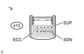
Text in Illustration *a Front view of wire harness connector
(to Spiral Cable Sub-assembly)
Measure the resistance according to the value(s) in the table below when the shift paddle switch is moved to each position.
Standard Resistance Tester Connection Switch Condition Specified Condition z13-6 (SUP) - z13-7 (ECC) Pull "+" continuously
(Up-shift)
Below 1 Ω Release 10 kΩ or higher z13-12 (SDN) - z13-7 (ECC) Pull "-" continuously
(Down-shift)
Below 1 Ω Release 10 kΩ or higher
NG
INSPECT TRANSMISSION SHIFT SWITCH ASSEMBLY (SHIFT PADDLE SWITCH) Click here
OK
-
-
INSPECT SPIRAL CABLE SUB-ASSEMBLY
-
Inspect the spiral cable sub-assembly Click here.
NG
REPLACE SPIRAL CABLE SUB-ASSEMBLY Click here
OK
CHECK FOR INTERMITTENT PROBLEMS Click here
-
-
INSPECT TRANSMISSION SHIFT SWITCH ASSEMBLY (SHIFT PADDLE SWITCH)
-
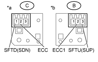
Text in Illustration *a Component without harness connected
(Shift paddle switch LH)
*b Component without harness connected
(Shift paddle switch RH)
Disconnect the connector from the transmission shift switch LH and RH.
-
Measure the resistance according to the value(s) in the table below.
Standard Resistance Transmission Shift Switch LH: Tester Connection Switch Condition Specified Condition C-2 (ECC) - C-1 (SFTD) Pull "-" continuously
(Down-shift)
Below 1 Ω Release 10 kΩ or higher Transmission Shift Switch RH: Tester Connection Switch Condition Specified Condition B-3 (SFTU) - B-2 (ECC1) Pull "+" continuously
(Up-shift)
Below 1 Ω Release 10 kΩ or higher
NG
REPLACE TRANSMISSION SHIFT SWITCH ASSEMBLY (SHIFT PADDLE SWITCH) Click here
OK
-
-
INSPECT NO. 1 SWITCH WIRE
-
Connect the transmission shift switch LH and RH connector.
-
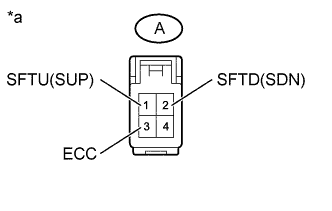
Text in Illustration *a Front view of wire harness connector
(to Steering Pad Switch Connector)
Disconnect the No.1 switch wire from steering pad switch connector.
-
Measure the resistance according to the value(s) in the table below.
Standard Resistance Tester Connection Switch Condition Specified Condition A-2 (SFTD) - A-3 (ECC) Pull "-" continuously
(Down-shift)
Below 1 Ω Release 10 kΩ or higher A-1 (SFTU) - A-3 (ECC) Pull "+" continuously
(Down-shift)
Below 1 Ω Release 10 kΩ or higher
NG
REPLACE NO. 1 SWITCH WIRE Click here
OK
REPAIR OR REPLACE STEERING PAD SWITCH ASSEMBLY
-