AUTOMATIC TRANSAXLE SYSTEM Transmission Control Switch Circuit
DESCRIPTION
When the shift lever is in S and it is moved toward "-" or "+", it is possible to select different shift ranges (1st through 6th ranges).
Moving the shift lever toward "+" increases the shift range by one, and moving the shift lever toward "-" decreases the shift range by one.
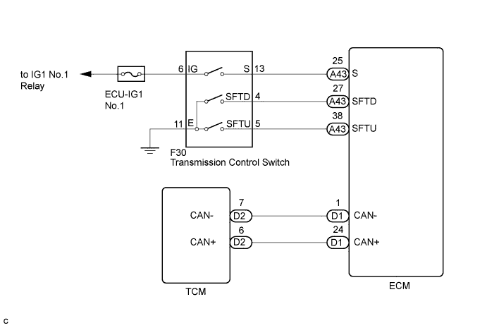
WIRING DIAGRAM
INSPECTION PROCEDURE
PROCEDURE
-
CHECK HARNESS AND CONNECTOR (BATTERY - TRANSMISSION CONTROL SWITCH)
-
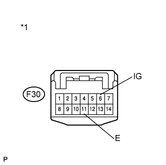
Text in Illustration *1 Front view of wire harness connector
(to Transmission Control Switch)
Disconnect the transmission control switch connector of shift lock control unit assembly.
-
Measure the voltage according to the value(s) in the table below.
Standard Voltage Tester Connection Condition Specified Condition F30-6 (IG) - Body ground or other terminals Engine switch on (IG) 11 to 14 V Engine switch off Below 1 V
NG 
REPAIR OR REPLACE HARNESS OR CONNECTOR
OK 
-
-
CHECK HARNESS AND CONNECTOR (TRANSMISSION CONTROL SWITCH - BODY GROUND)
-
Text in Illustration *1 Front view of wire harness connector
(to Transmission Control Switch)
Measure the resistance according to the value(s) in the table below.
Standard Resistance Tester Connection Condition Specified Condition F30-11 (E) - Body ground or other terminals Always Below 1 Ω
NG
REPAIR OR REPLACE HARNESS OR CONNECTOR
OK
-
-
INSPECT SHIFT LOCK CONTROL UNIT ASSEMBLY (TRANSMISSION CONTROL SWITCH)
-
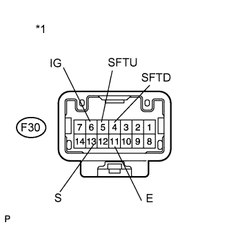
Text in Illustration *1 Component without harness connected
(Transmission Control Switch)
Measure the resistance between each terminal of the transmission control switch when the shift lever is moved to each position.
Standard Resistance Tester Connection Condition Specified Condition 6 (IG) - 13 (S) Shift lever in S, "+" or "-" Below 1 Ω Shift lever not in S, "+" or "-" 10 kΩ or higher 5 (SFTU) - 11 (E) Shift lever held in "+"
(Up-shift)
Below 1 Ω Shift lever not held in "+" 10 kΩ or higher 4 (SFTD) - 11 (E) Shift lever held in "-"
(Down-shift)
Below 1 Ω Shift lever not held in "-" 10 kΩ or higher
NG
REPLACE SHIFT LOCK CONTROL UNIT ASSEMBLY (TRANSMISSION CONTROL SWITCH) Click here
OK
-
-
CHECK HARNESS AND CONNECTOR (TRANSMISSION CONTROL SWITCH - ECM)
-
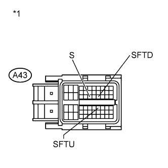
Text in Illustration *1 Front view of wire harness connector
(to ECM)
Connect the transmission control switch connector.
-
Disconnect the ECM connector.
-
Turn the engine switch on (IG).
-
Measure the voltage according to the value(s) in the table below.
Standard Voltage Tester Connection Condition Specified Condition A43-25 (S) - Body ground or other terminals
-
Engine switch on (IG)
-
Shift lever in S, "+" or "-"
11 to 14 V A43-25 (S) - Body ground or other terminals
-
Engine switch on (IG)
-
Shift lever not in S, "+" or "-"
Below 1 V -
-
Turn the engine switch off.
-
Disconnect the spiral cable connector.
-
Measure the resistance according to the value(s) in the table below.
Standard Resistance Tester Connection Condition Specified Condition A43-38 (SFTU) - Body ground or other terminals Shift lever held in "+"
(Up-shift)
Below 1 Ω Shift lever not held in "+" 10 kΩ or higher A43-27 (SFTD) - Body ground or other terminals Shift lever held in "-"
(Down-shift)
Below 1 Ω Shift lever not held in "-" 10 kΩ or higher
NG
REPAIR OR REPLACE HARNESS OR CONNECTOR
OK 
PROCEED TO NEXT SUSPECTED AREA SHOWN IN PROBLEM SYMPTOMS TABLE Click here
-