AUTOMATIC TRANSAXLE SYSTEM, Diagnostic DTC:U0100

| DTC Code | DTC Name |
|---|---|
| U0100 | Lost Communication with ECM / PCM "A" |
DESCRIPTION
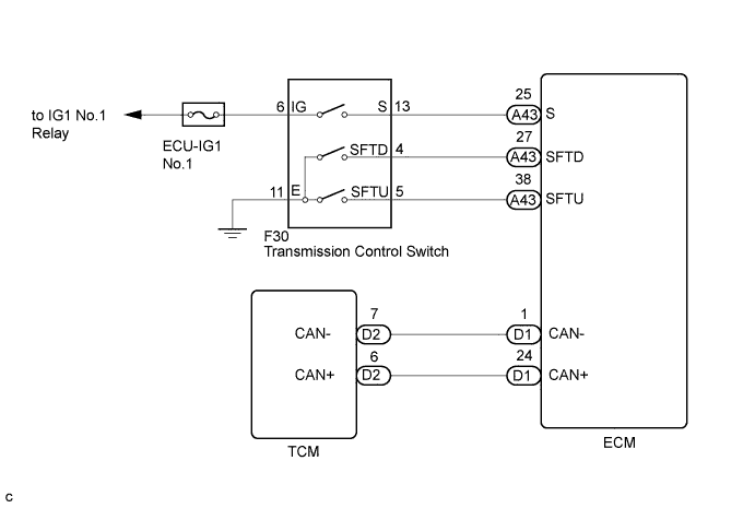
The engine control unit communicates with the TCM using the Controller Area Network (CAN).
If there is a problem in this communication, the TCM sets a DTC.
| DTC No. | DTC Detection Condition | Trouble Area |
|---|---|---|
| U0100 | Following conditions are met for 1.25 seconds (1 trip detection logic):
|
|
WIRING DIAGRAM
INSPECTION PROCEDURE
Tech Tips
-
Refer to inspection procedure for CAN communication system.
-
If the CAN communication malfunctions, the TCM cannot receive the current data from the ECM. In this case, the freeze frame data output from the TCM has not been updated, so the data will not be useful for the inspection. However, reading the Data List as the first step in troubleshooting is effective to find malfunctions.
-
The malfunction area can be checked using the Bus Check function on the intelligent tester Click here.
PROCEDURE
-
CHECK ECU TERMINAL VOLTAGE (+B AND E1 TERMINALS)
-
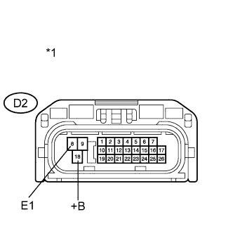
Text in Illustration *1 Front view of wire harness connector
(to TCM)
Disconnect the TCM connector.
-
Turn the engine switch on (IG).
-
Measure the voltage according to the value(s) in the table below.
Standard Voltage Tester Connection Switch Condition Specified Condition D2-18 (+B) - D2-8 (E1) Engine switch on (IG) 9 to 14 V -
Turn the engine switch off.
-
Measure the resistance according to the value(s) in the table below.
Standard Resistance Tester Connection Condition Specified Condition D2-8 (E1) - Body ground Always Below 1 Ω
NG 
REPAIR OR REPLACE HARNESS OR CONNECTOR
OK 
-
-
CHECK HARNESS AND CONNECTOR (TCM - ECM)
-
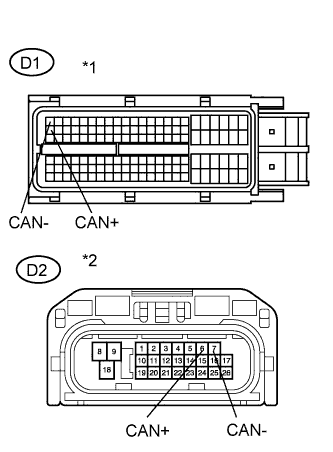
Text in Illustration *1 Front view of wire harness connector
(to ECM)
*2 Front view of wire harness connector
(to TCM)
Disconnect the TCM connector.
-
Disconnect the ECM connector.
-
Measure the resistance according to the value(s) in the table below.
Standard Resistance Tester Connection Condition Specified Condition D2-6 (CAN+) - D1-24 (CAN+) Always Below 1 Ω D2-7 (CAN-) - D1-1 (CAN-) Always Below 1 Ω D2-6 (CAN+) or D1-24 (CAN+) - Body ground or other terminals Always 1 MΩ or higher D2-7 (CAN-) or D1-1 (CAN-) - Body ground or other terminals Always 1 MΩ or higher
NG
REPAIR OR REPLACE HARNESS OR CONNECTOR
OK
-
-
CHECK IF DTC OUTPUT RECURS
-
Connect the intelligent tester to the DLC3.
-
Clear the DTCs.
-
Replace the TCM.
Tech Tips
Replace the TCM with a TCM from a normally functioning vehicle of the same model.
-
Start the engine.
-
Read the DTCs.
Result Display (DTC Output) Proceed to U0100 A No DTC B
B
REPLACE TCM Click here
A 
REPLACE ECM Click here
-