AUTOMATIC TRANSAXLE SYSTEM TERMINALS OF ECU

-
TCM

Tech Tips
Each TCM terminal standard voltage is shown in the table below.
In the table, first follow the information under "Condition". Look under "Terminal No. (Symbol)" for the terminals to be inspected. The standard voltage between the terminals is shown under "Specified Condition".
Use the illustration above as a reference for the TCM terminals.
Terminal No. (Symbol) Wiring Color Terminal Description Condition Specified Condition D2-15 (R) - D2-8 (E1) W - BR R shift position switch signal Engine switch on (IG) and shift lever in R 11 to 14 V Engine switch on (IG) and shift lever in any position except R Below 1 V D2-16 (D) - D2-8 (E1) Y - BR D shift position switch signal Engine switch on (IG) and shift lever in D and S 11 to 14 V Engine switch on (IG) and shift lever in any position except D and S Below 1 V D2-12 (STP) - D2-8 (E1) W-L - BR Stop light switch signal Brake pedal is depressed 7.5 to 14 V Brake pedal is released Below 1.5 V D2-11 (NSW) - D2-8 (E1) P - BR Park/neutral switch signal Engine switch on (IG) and shift lever in P or N Below 2 V Engine switch on (IG) and shift lever in any position except P or N 11 to 14 V D2-10 (STA) - D2-8 (E1) B - BR Starter signal Cranking (shift lever in P or N, engine switch START) 11 to 14 V Engine switch on (IG) and shift lever in any position except P or N Below 2 V D2-3 (SPD) - D2-8 (E1) LG - BR Speed signal from combination meter Vehicle speed 20 km/h (12 mph) Pulse generation
(see waveform 1)
D2-1 (BATT) - D2-8 (E1) G-R - BR Battery (for measuring battery voltage and for TCM memory) Always 9 to 14 V D2-13 (IGSW) - D2-8 (E1) G - BR Engine switch Engine switch on (IG) 9 to 14 V D2-18 (+B) - D2-8 (E1) L - BR Power source of TCM Engine switch on (IG) 9 to 14 V D2-6 (CAN+) - D2-8 (E1) L - BR CAN communication line Engine switch on (IG) Pulse generation
(see waveform 2)
D2-7 (CAN-) - D2-8 (E1) R - BR CAN communication line Engine switch on (IG) Pulse generation
(see waveform 3)
-
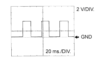
Waveform 1
Reference Terminal SPD - E1 Tool setting 2 V/DIV., 20 ms./DIV. Vehicle condition Vehicle speed 20 km/h (12 mph) -
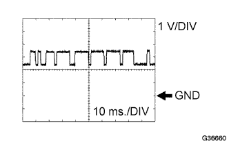
Waveform 2
Reference Terminal CAN+ - E1 Tool setting 1 V/DIV., 10 ms./DIV. Vehicle condition Engine is stopped, engine switch on (IG) -
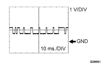
Waveform 3
Reference Terminal CAN- - E1 Tool setting 1 V/DIV., 10 ms./DIV. Vehicle condition Engine is stopped, engine switch on (IG)
-
-
ECM
Tech Tips
Each ECM terminal standard voltage is shown in the table below.
In the table, first follow the information under "Condition". Look under "Terminal No. (Symbol)" for the terminals to be inspected. The standard voltage between the terminals is shown under "Specified Condition".
Use the illustration below as a reference for the ECM terminals.
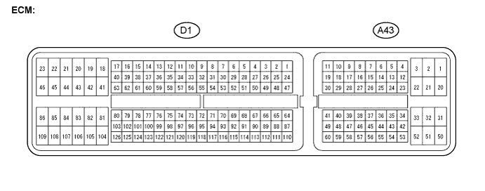
Terminal No. (Symbol) Wiring Color Terminal Description Condition Specified Condition A43-25 (S) - D1-81 (E1) L - BR S shift position switch signal Engine switch on (IG) and shift lever in S 11 to 14 V Engine switch on (IG) and shift lever in any position except S Below 1 V A43-38 (SFTU) - D1-81 (E1) W - BR Up shift switch signal Engine switch on (IG) and shift lever in S 11 to 14 V Engine switch on (IG) and shift lever in "+" (Up shift) Below 1 V A43-27 (SFTD) - D1-81 (E1) BE - BR Down shift switch signal Engine switch on (IG) and shift lever in S 11 to 14 V Engine switch on (IG) and shift lever in "-" (Down shift) Below 1 V