DYNAMIC RADAR CRUISE CONTROL SYSTEM ECU Power Source Circuit
DESCRIPTION
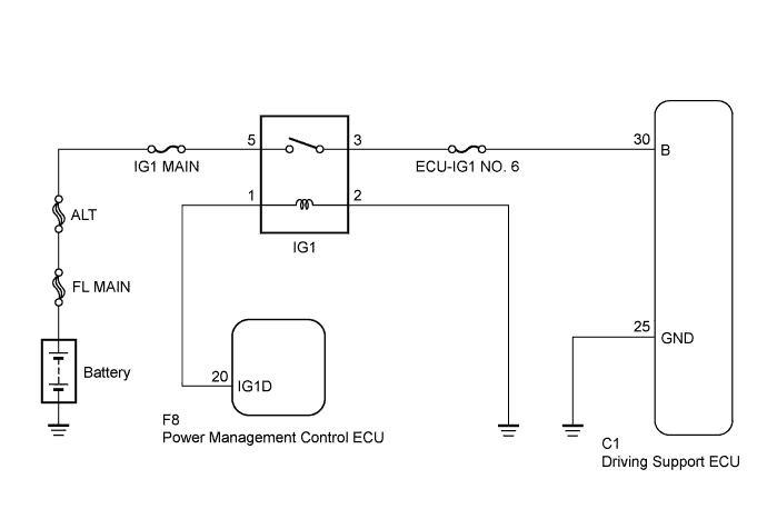
This circuit provides power to operate the driving support ECU. The driving support ECU determines information about the vehicle in front based on data from the radar sensor, and then decides how much acceleration and/or deceleration is needed to maintain the set distance. The driving support ECU also requests the skid control ECU to apply braking and to sound the buzzer.
WIRING DIAGRAM
INSPECTION PROCEDURE
Tech Tips
Inspect the fuses for circuits related to this system before performing the following inspection procedure.
PROCEDURE
-
CHECK DRIVING SUPPORT ECU (B VOLTAGE)
-
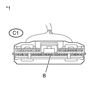
Text in Illustration *1 Front view of wire harness connector
(to Driving Support ECU)
Disconnect the driving support ECU connector.
-
Measure the voltage according to the value(s) in the table below.
Standard Voltage Tester Connection Switch Condition Specified Condition C1-30 (B) - Body ground Engine switch on (IG) 11 to 14 V -
Reconnect the driving support ECU connector.
NG 
INSPECT IGNITION RELAY NO. 1 Click here
OK 
-
-
CHECK HARNESS AND CONNECTOR (DRIVING SUPPORT ECU - BODY GROUND)
-
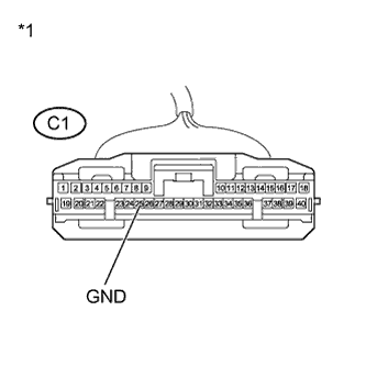
Text in Illustration *1 Front view of wire harness connector
(to Driving Support ECU)
Disconnect the driving support ECU connector.
-
Measure the resistance according to the value(s) in the table below.
Standard Resistance Tester Connection Condition Specified Condition C1-25 (GND) - Body ground Always Below 1 Ω -
Reconnect the driving support ECU connector.
NG 
REPAIR OR REPLACE HARNESS OR CONNECTOR
OK 
PROCEED TO NEXT SUSPECTED AREA SHOWN IN PROBLEM SYMPTOMS TABLE Click here
-
-
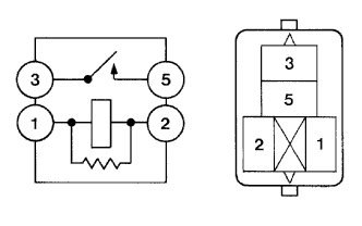
INSPECT IGNITION RELAY NO. 1
-
Remove the IG1 relay from the engine room relay block.
-
Measure the resistance according to the value(s) in the table below.
Standard Resistance Tester Connection Condition Specified Condition 3 - 5 No battery voltage applied between terminals 1 and 2 10 kΩ or higher 3 - 5 Battery voltage applied between terminals 1 and 2 Below 1 Ω -
Reinstall the IG1 relay.
NG
REPLACE IGNITION RELAY NO. 1
OK
-
-
CHECK HARNESS AND CONNECTOR (DRIVING SUPPORT ECU - ENGINE ROOM RELAY BLOCK)
-
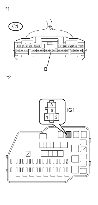
Text in Illustration *1 Front view of wire harness connector
(to Driving Support ECU)
*2 Engine Room Relay Block Disconnect the driving support ECU connector.
-
Remove the IG1 relay from the engine room relay block.
-
Measure the resistance according to the value(s) in the table below.
Standard Resistance Tester Connection Condition Specified Condition C1-30 (B) - 3 (IG1 relay) Always Below 1 Ω -
Install the IG1 relay.
-
Reconnect the driving support ECU connector.
NG
REPAIR OR REPLACE HARNESS OR CONNECTOR
OK
-
-
CHECK HARNESS AND CONNECTOR (IG1 RELAY POWER SOURCE CIRCUIT)
-
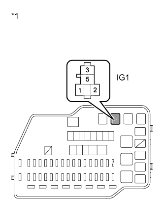
Text in Illustration *1 Engine Room Relay Block Disconnect the IG1 relay from the engine room relay block.
-
Measure the voltage according to the value(s) in the table below.
Standard Voltage Tester Connection Switch Condition Specified Condition 5 (IG1 relay) - Body ground Always 11 to 14 V -
Reconnect the IG1 relay.
NG
REPAIR OR REPLACE HARNESS OR CONNECTOR
OK
-
-
CHECK HARNESS AND CONNECTOR (IG1 RELAY - BODY GROUND)
-
Text in Illustration *1 Engine Room Relay Block Disconnect the IG1 relay from the engine room relay block.
-
Measure the resistance according to the value(s) in the table below.
Standard Resistance Tester Connection Condition Specified Condition 2 (IG1 relay) - Body ground Always Below 1 Ω -
Reconnect the IG1 relay.
NG
REPAIR OR REPLACE HARNESS OR CONNECTOR
OK
-
-
CHECK HARNESS AND CONNECTOR
-
Disconnect the power management control ECU connector.
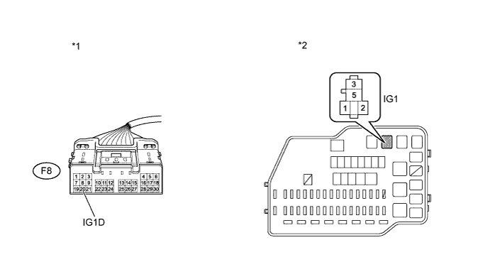
Text in Illustration *1 Front view of wire harness connector
(to Power Management Control ECU)
*2 Engine Room Relay Block -
Remove the IG1 relay from the engine room relay block.
-
Measure the resistance according to the value(s) in the table below.
Standard Resistance (Check for Open) Tester Connection Condition Specified Condition 1 (IG1 relay terminal) - F8-20 (IG1D) Always Below 1 Ω Standard Resistance (Check for Short) Tester Connection Condition Specified Condition 1 (IG1 relay terminal) - F8-20 (IG1D) - Body ground Always 10 kΩ or higher -
Reconnect the power management control ECU connector.
-
Reinstall the IG1 relay.
NG
REPAIR OR REPLACE HARNESS OR CONNECTOR
OK
GO TO ENTRY AND START SYSTEM (FOR START FUNCTION) Click here
-