DYNAMIC RADAR CRUISE CONTROL SYSTEM, Diagnostic DTC:U0235

| DTC Code | DTC Name |
|---|---|
| U0235 | Lost Communication with Cruise Control Front Distance Range Sensor |
DESCRIPTION
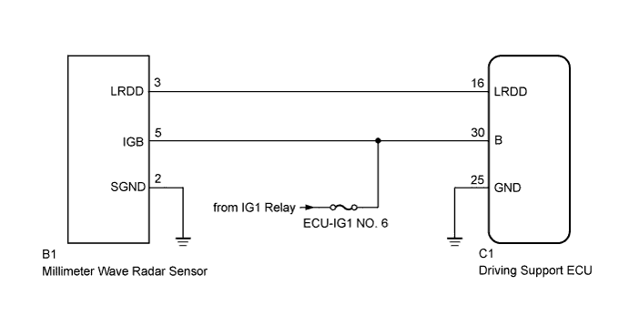
The millimeter wave radar sensor and driving support ECU transmit the data for general vehicle control and diagnosis function along the communication line. The millimeter wave radar sensor transmits information about the vehicle in front to the driving support ECU.
| DTC No. | DTC Detection Condition | Trouble Area |
|---|---|---|
| U0235 | The ECM detects a communication error signal (from the millimeter wave radar sensor to the driving support ECU) for 0.15 sec. or more while the dynamic radar cruise control is in operation |
|
WIRING DIAGRAM
INSPECTION PROCEDURE
Note
When the millimeter wave radar sensor is replaced with a new one, adjustment of the radar sensor beam axis must be performed Click here.
PROCEDURE
-
CHECK HARNESS AND CONNECTOR (DRIVING SUPPORT ECU - MILLIMETER WAVE RADAR SENSOR)
-
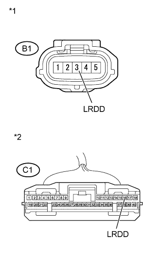
Text in Illustration *1 Front view of wire harness connector
(to Millimeter Wave Radar Sensor)
*2 Front view of wire harness connector
(to Driving Support ECU)
Disconnect the driving support ECU and millimeter wave radar sensor connectors.
-
Measure the resistance according to the value(s) in the table below.
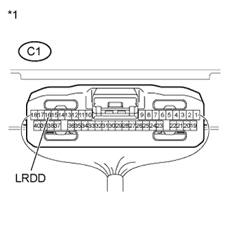
Standard Resistance Tester Connection Condition Specified Condition C1-16 (LRDD) - B1-3 (LRDD) Always Below 1 Ω C1-16 (LRDD) - Body ground Always 10 kΩ or higher -
Reconnect the driving support ECU and millimeter wave radar sensor connectors.
NG 
REPAIR OR REPLACE HARNESS OR CONNECTOR
OK 
-
-
CHECK HARNESS AND CONNECTOR (MILLIMETER WAVE RADAR SENSOR - BODY GROUND)
-
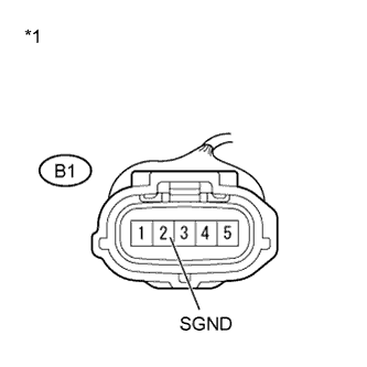
Text in Illustration *1 Front view of wire harness connector
(to Millimeter Wave Radar Sensor)
Disconnect the millimeter wave radar sensor connector.
-
Measure the resistance according to the value(s) in the table below.
Standard Resistance Tester Connection Condition Specified Condition B1-2 (SGND) - Body ground Always Below 1 Ω -
Reconnect the millimeter wave radar sensor connector.
NG
REPAIR OR REPLACE HARNESS OR CONNECTOR
OK
-
-
CHECK HARNESS AND CONNECTOR (DRIVING SUPPORT ECU POWER SOURCE CIRCUIT)
-
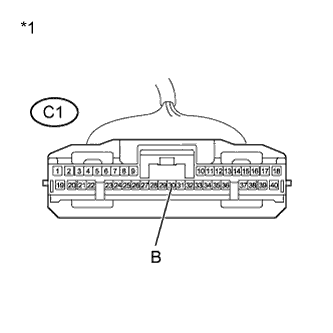
Text in Illustration *1 Front view of wire harness connector
(to Driving Support ECU)
Disconnect the driving support ECU connector.
-
Measure the voltage according to the value(s) in the table below.
Standard Voltage Tester Connection Switch Condition Specified Condition C1-30 (B) - Body ground Engine switch on (IG) 11 to 14 V -
Reconnect the driving support ECU connector.
NG
REPAIR OR REPLACE HARNESS OR CONNECTOR
OK
-
-
CHECK HARNESS AND CONNECTOR (DRIVING SUPPORT ECU - BODY GROUND)
-
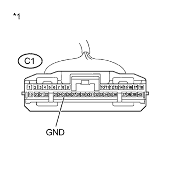
Text in Illustration *1 Front view of wire harness connector
(to Driving Support ECU)
Disconnect the driving support ECU connector.
-
Measure the resistance according to the value(s) in the table below.
Standard Resistance Tester Connection Condition Specified Condition C1-25 (GND) - Body ground Always Below 1 Ω -
Reconnect the driving support ECU connector.
NG
REPAIR OR REPLACE HARNESS OR CONNECTOR
OK
-
-
CHECK DRIVING SUPPORT ECU
-
Text in Illustration *1 Component with harness connected:
(Driving Support ECU)
Measure the voltage according to the value(s) in the table below.
Standard Voltage Tester Connection Switch Condition Specified Condition C1-16 (LRDD) - Body ground Engine switch on (IG) 4.5 to 5.5 V
NG
REPLACE DRIVING SUPPORT ECU Click here
OK
-
-
REPLACE MILLIMETER WAVE RADAR SENSOR
-
Replace the millimeter wave radar sensor Click here.
-
Adjust the millimeter wave radar sensor Click here.
NEXT
-
-
CHECK DTC OUTPUT
-
Clear the DTCs Click here.
-
Perform the following to make sure that the DTC detection conditions are met.
Tech Tips
If the detection conditions are not met, the malfunction cannot be detected.
-
Drive the vehicle at a speed of 50 km/h (31 mph) or more.
-
Turn the cruise control main switch on.
-
Push the -SET switch to activate the cruise control.
-
-
Check for DTCs Click here.
Result Result Proceed to DTC is not output A DTC U0235 is output B
B
REPLACE DRIVING SUPPORT ECU Click here
A 
END
-