DYNAMIC RADAR CRUISE CONTROL SYSTEM, Diagnostic DTC:U0100, U0122, U0123, U0126, U0235, U1002, U1104

| DTC Code | DTC Name |
|---|---|
| U0100 | Lost Communication with ECM / PCM "A" |
| U0122 | Lost Communication with Vehicle Dynamics Control Module |
| U0123 | Lost Communication with Yaw Rate Sensor Module |
| U0126 | Lost Communication with Steering Angle Sensor Module |
| U0235 | Lost Communication with Cruise Control Front Distance Range Sensor |
| U1002 | Lost Communication with Gateway Module |
| U1104 | Lost Communication with Driving Support ECU |
DESCRIPTION
The ECM communicates several signals with each sensor and ECU by CAN communication circuit.
If there are any malfunctions in the communication circuit, one or more DTCs in the CAN communication system are stored.
| DTC No. | DTC Detection Condition | Trouble Area |
|---|---|---|
| U0100 | While the dynamic radar cruise control is either preparing for operation or operating, if the ECM continuously receives a communication cut off signal from the driving support ECU for more than a specific amount of time, the ECM records this communication cut off code |
|
| While the dynamic radar cruise control is either preparing for operation or operating, if the ECM continuously receives a communication cut off signal from the skid control ECU for a certain amount of time, the ECM records this communication cut off code |
|
|
| U0122 | While dynamic radar cruise control is either preparing for operation or operating, if communication data from the skid control ECU is invalid for a certain amount of time, the ECM records the communication cut off code |
|
| U0123 | While the dynamic radar cruise control is either preparing for operation or operating, the ECM continuously receives a yaw rate and acceleration sensor malfunction signal for a certain amount of time |
|
| U0126 | While the dynamic radar cruise control is either preparing for operation or operating, if the ECM continuously receives a steering sensor communication error signal for a certain amount of time, the driving support ECU sends a signal to the ECM to record this trouble code |
|
| U0126 | When the engine switch is on (IG), a communication error between the millimeter wave radar sensor and the driving support ECU is detected for approximately 5 seconds. |
|
| U0235 | When the engine switch is on (IG), a communication error between the millimeter wave radar sensor and the driving support ECU is detected for approximately 2 seconds. |
|
| U1002 | When the engine switch is on (IG), a communication error between the millimeter wave radar sensor and the driving support ECU is detected for approximately 2 seconds. |
|
| U1104 | When the engine switch is on (IG), a communication error between the driving support ECU and the millimeter wave radar sensor is detected for approximately 1 second. |
|
WIRING DIAGRAM

INSPECTION PROCEDURE
PROCEDURE
-
CHECK DTC (CAN COMMUNICATION SYSTEM)
-
Connect the intelligent tester to the DLC3.
-
Turn the engine switch on (IG).
-
Turn the intelligent tester on.
-
Enter the following menus: Powertrain / Radar Cruise / Trouble Codes.
-
Check for DTCs.
Result Result Proceed to DTC U0235 or U1104 is output A DTC U0235 and U1104 are not output B
B 
GO TO CAN COMMUNICATION SYSTEM Click here
A 
-
-
CHECK CAN COMMUNICATION SYSTEM
-
Select "CAN Bus Check" from the "System Selection Menu" on the intelligent tester.
-
Select "Communication Malfunction Check" from the "CAN Bus Check" screen, and then select "OK".
OK CAN communication is normal.
NG
GO TO CAN COMMUNICATION SYSTEM Click here
OK
-
-
CHECK HARNESS AND CONNECTOR (DRIVING SUPPORT ECU - MILLIMETER WAVE RADAR SENSOR)
-
Disconnect the driving support ECU connector.
-
Disconnect the millimeter wave radar sensor connector.
-
Measure the resistance according to the value(s) in the table below.
Standard Resistance Tester Connection Condition Specified Condition C1-40 (CA1P) - B1-4 (CA1P) Always Below 1 Ω C1-18 (CA1N) - B1-3 (CA1N) Always Below 1 Ω C1-40 (CA1P) or B1-4 (CA1P) - Body ground Always 10 kΩ or higher C1-18 (CA1N) or B1-3 (CA1N) - Body ground Always 10 kΩ or higher -
Reconnect the millimeter wave radar sensor connector.
-
Reconnect the driving support ECU connector.
NG
REPAIR OR REPLACE HARNESS OR CONNECTOR
OK
-
-
CHECK TERMINAL VOLTAGE (POWER SOURCE OF DRIVING SUPPORT ECU)
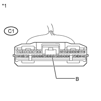
Text in Illustration *1 Front view of wire harness connector
(to Driving Support ECU)
-
Disconnect the driving support ECU connector.
-
Measure the voltage and resistance according to the value(s) in the table below.
Standard Voltage Tester Connection Condition Specified Condition C1-30 (B) - Body ground Engine switch on (IG) 11 to 14 V C1-30 (B) - Body ground Engine switch off Below 1 V -
Reconnect the driving support ECU connector.
NG
REPAIR OR REPLACE HARNESS OR CONNECTOR (DRIVING SUPPORT ECU - BODY GROUND)
OK
-
-
CHECK HARNESS AND CONNECTOR (DRIVING SUPPORT ECU - BODY GROUND)
-
Disconnect the driving support ECU connector.
-
Measure the resistance according to the value(s) in the table below.
Standard Resistance Tester Connection Condition Specified Condition C1-25 (GND) - Body ground Always Below 1 Ω -
Reconnect the driving support ECU connector.
NG
REPAIR OR REPLACE HARNESS OR CONNECTOR (DRIVING SUPPORT ECU - BODY GROUND)
OK
-
-
CHECK TERMINAL VOLTAGE (POWER SOURCE OF MILLIMETER WAVE RADAR SENSOR)
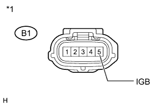
Text in Illustration *1 Front view of wire harness connector
(to Millimeter Wave Radar Sensor)
-
Disconnect the millimeter wave radar sensor connector.
-
Measure the voltage and resistance according to the value(s) in the table below.
Standard Voltage Tester Connection Condition Specified Condition B1-5 (IGB) - Body ground Engine switch on (IG) 11 to 14 V B1-5 (IGB) - Body ground Engine switch off Below 1 V -
Reconnect the millimeter wave radar sensor connector.
NG
REPAIR OR REPLACE HARNESS OR CONNECTOR (MILLIMETER WAVE RADAR SENSOR - BODY GROUND)
OK
-
-
CHECK HARNESS AND CONNECTOR (MILLIMETER WAVE RADAR SENSOR - BODY GROUND)
-
Disconnect the millimeter wave radar sensor connector.
-
Measure the resistance according to the value(s) in the table below.
Standard Resistance Tester Connection Condition Specified Condition B1-2 (SGND) - Body ground Always Below 1 Ω -
Reconnect the millimeter wave radar sensor connector.
NG
REPAIR OR REPLACE HARNESS OR CONNECTOR (MILLIMETER WAVE RADAR SENSOR - BODY GROUND)
OK
-
-
CHECK MILLIMETER WAVE RADAR SENSOR
-
Replace the millimeter wave radar sensor with a new one Click here.
-
Perform millimeter wave radar sensor adjustment Click here.
NEXT
-
-
CHECK DTC OUTPUT
-
Clear the DTCs Click here.
-
Make sure that the DTC detection conditions are met.
Tech Tips
If the detection conditions are not met, the system cannot detect the malfunction.
-
Check for DTCs Click here.
Note
When replacing the driving support ECU, always replace it with a new one. If a driving support ECU which was installed to another vehicle is used, the information stored in the driving support ECU will not match the information from the vehicle. As a result, a DTC may be stored.
Result Result Proceed to DTC U0235 and U1104 are not output A DTC U0235 or U1104 is output B
B
REPLACE DRIVING SUPPORT ECU Click here
A 
END
-