DYNAMIC RADAR CRUISE CONTROL SYSTEM TERMINALS OF ECU

-
CHECK DRIVING SUPPORT ECU

Terminal No. (Symbol) Wiring Color Terminal Description Condition Specified Condition C1-30 (B) - C1-25 (GND) P - W-B Battery Always 11 to 14 V C1-39 (CA2H) - C1-25 (GND) B - W-B CAN communication signal CAN communication circuit Pulse generation
(See waveform 1)
C1-17 (CA2L) - C1-25 (GND) W - W-B CAN communication signal CAN communication circuit Pulse generation
(See waveform 2)
C1-25 (GND) - Body ground W-B - Body ground Ground Always Below 1 V C1-7 (MODE) - C1-25 (GND) Y - W-B Steering pad switch signal (Distance control switch signal) Engine switch on (IG), Steering pad switch signal ON 0 to 2 V C1-7 (MODE) - C1-25 (GND) Y - W-B Steering pad switch signal (Distance control switch signal) Engine switch on (IG), Steering pad switch signal OFF 11 to 14 V C1-18 (CA1N) - C1-25 (GND) L - W-B CAN communication signal Engine switch on (IG) Pulse generation
(See waveform 3)
C1-40 (CA1P) - C1-25 (GND) B - W-B CAN communication signal Engine switch on (IG) Pulse generation
(See waveform 4)
C1-32 (WIP2) - C1-25 (GND) BE - W-B Wiper switch signal Engine switch on (IG), wiper switch HI position 11 to 14 V C1-32 (WIP2) - C1-25 (GND) BE - W-B Wiper switch signal Engine switch on (IG), wiper switch LO position Below 1 V
-
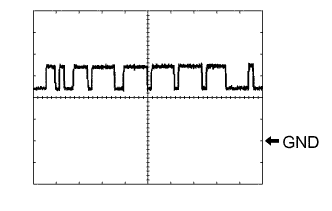
Waveform 1
-
CAN communication signal
Item Content Terminal Name C1-39 (CA2H) - C1-25 (GND) Tester Range 1 V/DIV., 10 μsec./DIV. Condition Engine switch on (IG) Tech Tips
The waveform varies depending on the CAN communication signal.
-
-
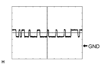
Waveform 2
-
CAN communication signal
Item Content Terminal Name C1-17 (CA2L) - C1-25 (GND) Tester Range 1 V/DIV., 10 μsec./DIV. Condition Engine switch on (IG) Tech Tips
The waveform varies depending on the CAN communication signal.
-
-

Waveform 3
-
CAN communication signal
Item Content Terminal Name C1-18 (CA1N) - C1-25 (GND) Tester Range 1 V/DIV., 10 μsec./DIV. Condition Engine switch on (IG) Tech Tips
The waveform varies depending on the CAN communication signal.
-
-
Waveform 4
-
CAN communication signal
Item Content Terminal Name C1-40 (CA1P) - C1-25 (GND) Tester Range 1 V/DIV., 10 μsec./DIV. Condition Engine switch on (IG) Tech Tips
The waveform varies depending on the CAN communication signal.
-
-
-
CHECK ECM (for 2GR-FE)
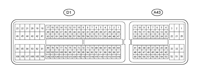
Terminal No. (Symbol) Wiring Color Terminal Description Condition Specified Condition A43-16 (TC) - D1-81 (E1) L - BR Ground Engine switch on (IG) 11 to 14 V A43-16 (TC) - D1-81 (E1) L - BR Ground Terminals TC and CG of DLC3 connected Below 1 V A43-35 (ST1-) - D1-81 (E1) BR - BR Stop light signal Engine switch on (IG), Brake pedal depressed (Stop light switch on) Below 1 V A43-35 (ST1-) - D1-81 (E1) BR - BR Stop light signal Engine switch on (IG), Brake pedal released (Stop light switch off) 11 to 14 V A43-36 (STP) - D1-81 (E1) B - BR Stop light signal Engine switch on (IG), Brake pedal released (Stop light switch off) Below 1 V A43-36 (STP) - D1-81 (E1) B - BR Stop light signal Engine switch on (IG), Brake pedal depressed (Stop light switch on) 11 to 14 V A43-37 (CCHG) - D1-81 (E1) GR - BR Distance control switch signal Engine switch on (IG), Cruise control main switch on, MODE switch on Below 1 V A43-37 (CCHG) - D1-81 (E1) GR - BR Distance control switch signal Engine switch on (IG), Cruise control main switch on, MODE switch off 11 to 14 V A43-44 (LGND) - Body ground V - Body ground Ground Always Below 1 V A43-45 (CCS) - D1-81 (E1) P - BR Cruise control main switch signal Engine switch on (IG) 11 to 14 V A43-45 (CCS) - D1-81 (E1) P - BR Cruise control main switch signal Engine switch on (IG), CANCEL switch on 6.6 to 10.1 V A43-45 (CCS) - D1-81 (E1) P - BR Cruise control main switch signal Engine switch on (IG), - SET switch on 4.5 to 7.1 V A43-45 (CCS) - D1-81 (E1) P - BR Cruise control main switch signal Engine switch on (IG), + RES switch on 2.3 to 4.0 V A43-45 (CCS) - D1-81 (E1) P - BR Cruise control main switch signal Engine switch on (IG), Main switch on Below 1 V D1-81 (E1) - Body ground BR - Body ground Ground Always Below 1 V If the value is not within the specified range, the ECM may have a malfunction.