OIL PUMP REMOVAL

-
PRECAUTION (w/ Air Suspension)
CAUTION:
Be sure to read Precaution thoroughly before service Click here.
-
REMOVE ENGINE ASSEMBLY WITH TRANSAXLE
Tech Tips
-
INSTALL ENGINE ON ENGINE STAND
-
Install the engine onto an engine stand with the bolts.
-
-
REMOVE ENGINE HANGER
-
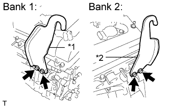
Text in Illustration *1 No. 1 engine hanger *2 No. 2 engine hanger Remove the 4 bolts, No. 1 and No. 2 engine hangers.
-
-
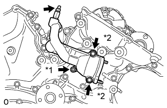
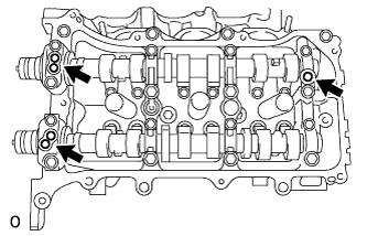
REMOVE NO. 1 OIL PIPE
-
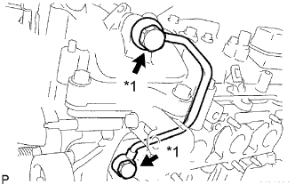
Text in Illustration *1 Oil Pipe Union Remove the 2 oil pipe unions, gaskets and No. 1 oil pipe.
-
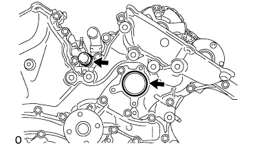
Remove the oil control valve filter LH and gaskets.
-
-
REMOVE OIL PIPE
-
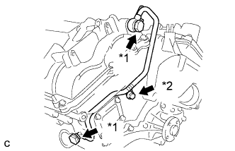
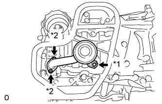
Text in Illustration *1 Oil Pipe Union *2 Bolt Remove the bolt.
-
Remove the 2 oil pipe unions and oil pipe.
-
Remove the oil control valve filter RH and gaskets.
-
-
REMOVE CRANKSHAFT PULLEY
-
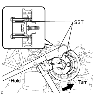
Using SST, loosen the crankshaft pulley bolt.
- SST
- 09213-70011 ( 09213-70020 )
- 09330-00021
-
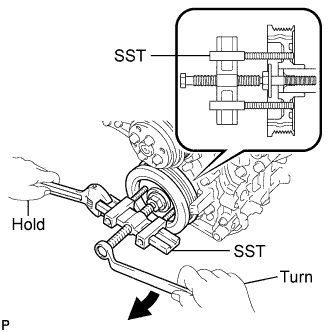
Using SST, remove the crankshaft pulley bolt and crankshaft pulley.
- SST
- 09950-50013 ( 09951-05010, 09952-05010, 09953-05020, 09954-05021 )
-
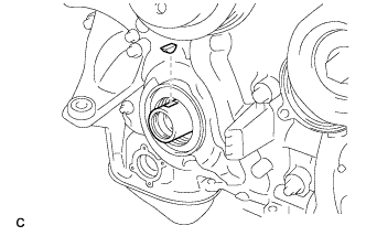
Remove the pulley set key from the crankshaft.
-
-
SEPARATE OIL COOLER PIPE
-
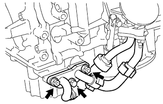
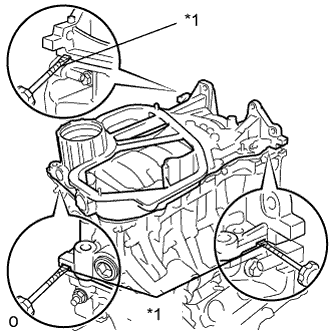
Remove the bolt and 2 nuts, and disconnect the oil cooler pipe from the oil pan sub-assembly.
-
Remove the gasket from the oil pan sub-assembly.
-
-
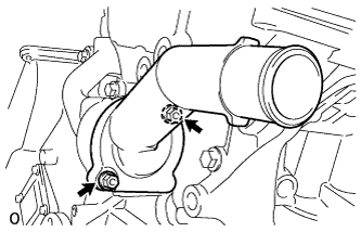
REMOVE WATER INLET HOUSING
-
Remove the 2 nuts, water inlet and thermostat.
-
Remove the gasket.
-
Remove the 2 stud bolts.
-
Separate the No. 1 water by-pass hose from the water inlet housing.
-
Text in Illustration *1 Nut *2 Bolt Remove the drain cock plug.
-
Remove the drain cock assembly.
-
Remove the 2 bolts, nut, and water inlet housing.
-
Remove the 2 O-rings.
-
-
REMOVE CYLINDER HEAD COVER SUB-ASSEMBLY
-
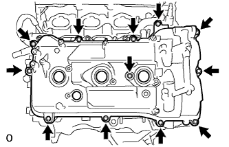
Remove the 12 bolts, seal washer, cylinder head cover sub-assembly and cylinder head cover gasket.
-
Remove the 3 gaskets.
-
-
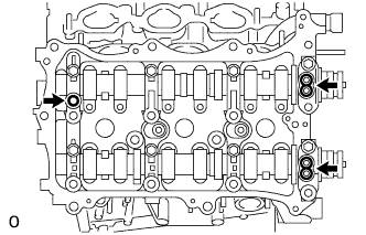
REMOVE CYLINDER HEAD COVER SUB-ASSEMBLY LH
-
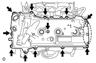
Text in Illustration *1 Baffle Plate Remove the 12 bolts, seal washer, cylinder head cover sub-assembly LH and cylinder head cover gasket.
Note
The baffle plate is located on the back of the portion shown in the illustration. Do not damage the baffle plate when removing the cylinder head cover sub-assembly LH.
-
Remove the 3 gaskets.
-
-
REMOVE NO. 2 OIL PAN SUB-ASSEMBLY
-
Text in Illustration *1 Nut Remove the 16 bolts and 2 nuts.
-
Insert the blade of the oil pan seal cutter between the oil pans. Cut through the applied sealer and remove the No. 2 oil pan sub-assembly.
Note
Be careful not to damage the contact surfaces of the oil pans.
-
Using an E6 "TORX" socket wrench, remove the 2 stud bolts.
-
-
REMOVE OIL STRAINER SUB-ASSEMBLY
-
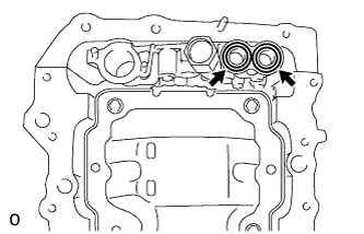
Text in Illustration *1 Bolt *2 Nut Remove the bolt, 2 nuts, oil strainer sub-assembly and gasket.
-
Using an E6 "TORX" socket wrench, remove the 2 stud bolts.
-
-
REMOVE OIL PAN SUB-ASSEMBLY
-
Text in Illustration *1 Nut Remove the 16 bolts and 2 nuts.
Tech Tips
Be sure to clean the bolts and stud bolts and check the threads for cracks or other damage.
-
Text in Illustration *1 Protective Tape Remove the oil pan sub-assembly by prying between the oil pan sub-assembly and cylinder block sub-assembly with a screwdriver.
Note
Be careful not to damage the contact surfaces of the cylinder block and oil pan.
Tech Tips
Tape the screwdriver tip before use.
-
Remove the 2 O-rings.
-
Using an E8 "TORX" socket wrench, remove the 2 stud bolts.
-
-
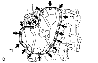
REMOVE TIMING CHAIN COVER SUB-ASSEMBLY
-
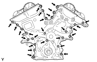
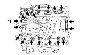
Remove the 23 bolts and 2 nuts shown in the illustration.
-
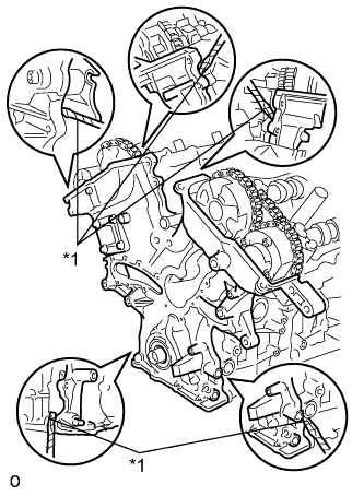
Text in Illustration *1 Protective Tape Remove the timing chain cover by prying between the timing chain cover and cylinder head or cylinder block with a screwdriver.
Note
Be careful not to damage the contact surfaces of the cylinder head, cylinder block and chain cover.
Tech Tips
Tape the screwdriver tip before use.
-
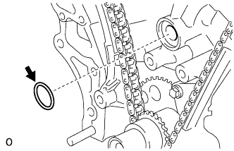
Remove the gasket.
-
-
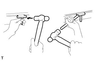
REMOVE TIMING CHAIN COVER OIL SEAL
-
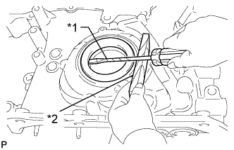
Text in Illustration *1 Protective Tape *2 Wooden Block Using a screwdriver, pry out the oil seal.
Tech Tips
Tape the screwdriver tip before use.
-