EXHAUST PIPE INSTALLATION

-
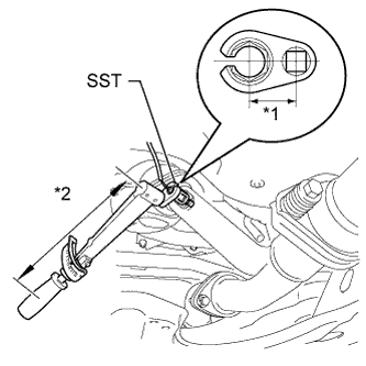
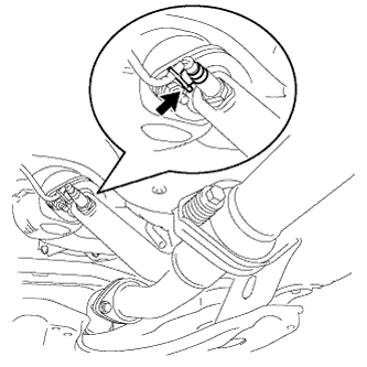
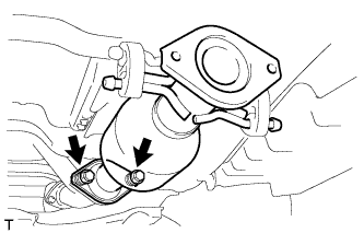
INSTALL NO. 2 OXYGEN SENSOR (for Bank 2 Sensor 2)
-

Text in Illustration *1 Fulcrum Length
30 mm
*2 Fulcrum Length
300 mm
Using SST, install the No. 2 oxygen sensor to the front exhaust pipe assembly.
- SST
- 09224-00010
- Torque:
- without SST
- 44 N*m { 449 kgf*cm, 33 ft.*lbf }
- with SST
- 40 N*m { 408 kgf*cm, 30 ft.*lbf }
Note
-
The "with SST" torque value is effective when using SST with a fulcrum length of 30 mm (1.18 in.).
-
The "with SST" torque value is effective when using a torque wrench with a fulcrum length of 300 mm (11.81 in.) Click here.
-
The "with SST" torque value is effective when SST is parallel to the torque wrench.
-
-
INSTALL FRONT EXHAUST PIPE ASSEMBLY
-
Install a new gasket to the front exhaust pipe assembly.
-
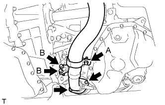
Install the front exhaust pipe assembly with the 2 nuts and 2 bolts (B).
- Torque:
- Bolt B
- 21 N*m { 214 kgf*cm, 15 ft.*lbf }
- Nut
- 55 N*m { 561 kgf*cm, 40 ft.*lbf }
-
Tighten the bolt (A).
- Torque:
- Bolt A
- 21 N*m { 214 kgf*cm, 15 ft.*lbf }
-
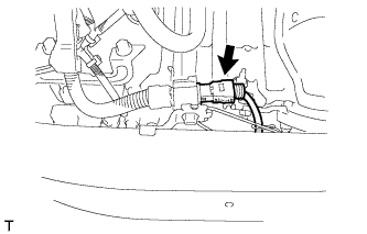
Connect the No. 2 oxygen sensor connector (for Bank 2 Sensor 2).
-
-
INSTALL FRONT NO. 3 EXHAUST PIPE SUB-ASSEMBLY
-
Install 2 new gaskets to the front No. 3 exhaust pipe sub-assembly.
-
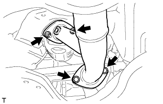
Install the front No. 3 exhaust pipe sub-assembly with the 2 bolts and 2 nuts.
- Torque:
- Bolt
- 55 N*m { 561 kgf*cm, 40 ft.*lbf }
- Nut
- 55 N*m { 561 kgf*cm, 40 ft.*lbf }
-
-
INSTALL OXYGEN SENSOR (for Bank 1 Sensor 2)
-
Text in Illustration *1 Fulcrum Length
30 mm
*2 Fulcrum Length
300 mm
Using SST, install the oxygen sensor to the center exhaust pipe assembly.
- SST
- 09224-00010
- Torque:
- without SST
- 44 N*m { 449 kgf*cm, 33 ft.*lbf }
- with SST
- 40 N*m { 408 kgf*cm, 30 ft.*lbf }
Note
-
The "with SST" torque value is effective when using SST with a fulcrum length of 30 mm (1.18 in.).
-
The "with SST" torque value is effective when using a torque wrench with a fulcrum length of 300 mm (11.81 in.) Click here.
-
The "with SST" torque value is effective when SST is parallel to the torque wrench.
-
Install the wire harness clamp bracket.
-
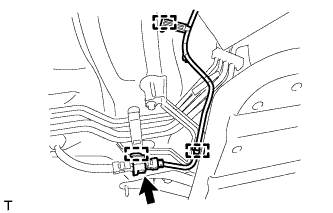
Connect the 3 clamps and oxygen sensor connector (for Bank 1 Sensor 2).
-
-
INSTALL CENTER EXHAUST PIPE ASSEMBLY
-
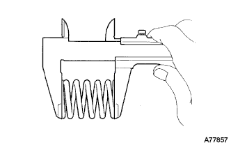
Using a vernier caliper, measure the free length of the compression springs.
Minimum length 41.5 mm (1.64 in.) If the free length is less than the minimum, replace the compression spring.
-
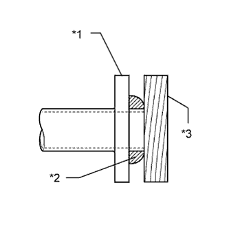
Fully insert a new gasket to the front No. 3 exhaust pipe sub-assembly.
-
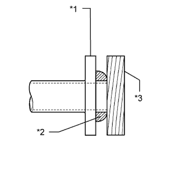
Text in Illustration *1 Front No. 3 Exhaust Pipe Sub-assembly *2 Gasket *3 Wooden Block Using a plastic hammer and wooden block, tap in the new gasket until its surface is flush with the front No. 3 exhaust pipe sub-assembly.
Note
-
Be sure to install the gasket in the correct direction.
-
Do not reuse the gasket.
-
Do not damage the gasket.
-
Do not push in the gasket by using the exhaust pipe when connecting it.
-
-
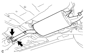
Connect the center exhaust pipe assembly to the 2 exhaust pipe supports.
-
Install the center exhaust pipe assembly with the 2 bolts and 2 compression springs.
- Torque:
- 43 N*m { 440 kgf*cm, 32 ft.*lbf }
-
-
INSTALL TAIL EXHAUST PIPE ASSEMBLY
-
Using a vernier caliper, measure the free length of the compression springs.
Minimum length 38.5 mm (1.52 in.) If the free length is less than the minimum, replace the compression spring.
-
Fully insert a new gasket to the center exhaust pipe assembly.
-
Text in Illustration *1 Center Exhaust Pipe Assembly *2 Gasket *3 Wooden Block Using a plastic hammer and wooden block, tap in the new gasket until its surface is flush with the center exhaust pipe assembly.
Note
-
Be sure to install the gasket in the correct direction.
-
Do not reuse the gasket.
-
Do not damage the gasket.
-
Do not push in the gasket by using the exhaust pipe when connecting it.
-
-
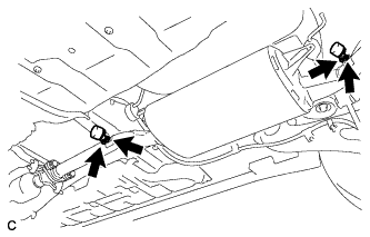
Connect the tail exhaust pipe assembly to the 4 exhaust pipe supports.
-
Install the tail exhaust pipe assembly with the 2 bolts and 2 compression springs.
- Torque:
- 43 N*m { 440 kgf*cm, 32 ft.*lbf }
-
-
INSTALL EXHAUST PIPE DAMPER
-
Install the 2 exhaust pipe dampers with the 4 bolts.
- Torque:
- 19 N*m { 194 kgf*cm, 14 ft.*lbf }
-
-
INSTALL FRONT FLOOR COVER LH
-
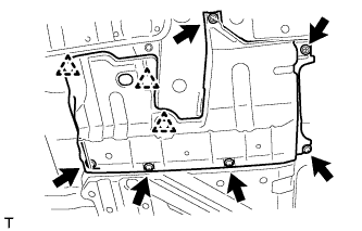
Connect the 3 clips.
-
Install the front floor cover LH with the 2 screws and 4 bolts.
-
-
INSPECT FOR EXHAUST GAS LEAK