INTAKE MANIFOLD INSTALLATION

-
INSTALL INTAKE MANIFOLD
-
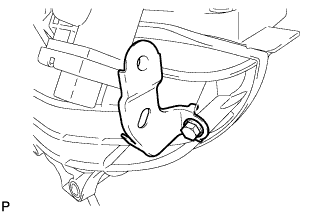
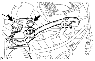
Install the wire harness clamp bracket with the bolt.
- Torque:
- 10 N*m { 102 kgf*cm, 7 ft.*lbf }
-
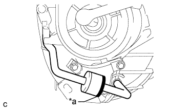
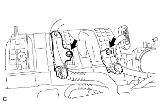
Text in Illustration *a Black Connect the 2 vacuum hoses and check that the check valve is installed as shown in the illustration.
-
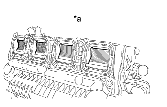
Text in Illustration *a Condition: Closed Check the tumble control valves.
Note
The tumble control valves may be damaged if they are not closed before installing the intake manifold.
Tech Tips
Connect the battery to the terminals of the actuator to operate the motor and close the valves Click here.
-
Install a new gasket to the intake manifold.
-
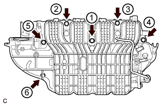
Install the intake manifold by tightening the 6 bolts in the sequence shown in the illustration.
- Torque:
- 21 N*m { 214 kgf*cm, 15 ft.*lbf }
-
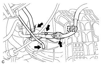
Connect the intake air control actuator connector and 2 wire harness clamps.
-
Install the wire harness clamp with the bolt.
- Torque:
- 10 N*m { 102 kgf*cm, 7 ft.*lbf }
-
Install the wire harness clamp bracket with the bolt.
- Torque:
- 10 N*m { 102 kgf*cm, 7 ft.*lbf }
-
Connect the wire harness clamp and connector.
-
Connect the fuel vapor feed hose and vacuum hose.
-
Install the 2 wire harness clamp brackets with the 2 bolts.
- Torque:
- 10 N*m { 102 kgf*cm, 7 ft.*lbf }
-
-
INSTALL FUEL DELIVERY PIPE SUB-ASSEMBLY
-
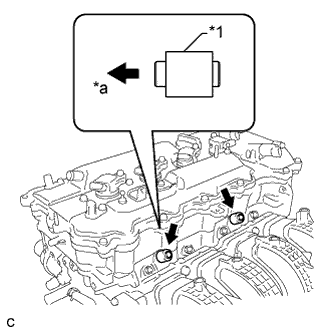
Text in Illustration *1 Fuel Delivery Spacer *a Cylinder Head Side Install the 2 fuel delivery spacers onto the cylinder head.
Tech Tips
Install the fuel delivery spacer so that the longer protrusion is on the cylinder head side.
-
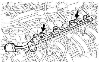
Install the fuel delivery pipe sub-assembly with the 4 fuel injector assemblies and install the 2 bolts.
- Torque:
- 21 N*m { 214 kgf*cm, 15 ft.*lbf }
Note
-
Do not drop the fuel injectors when installing the fuel delivery pipe sub-assembly.
-
Check that the fuel injector assemblies rotate smoothly after installing the fuel delivery pipe sub-assembly.
-
-
CONNECT UNION TO CONNECTOR TUBE HOSE
-
Connect the union to connector tube hose to the intake manifold.
-
-
CONNECT NO. 2 VENTILATION HOSE
-
Connect the No. 2 ventilation hose to the intake manifold.
-
-
INSTALL VACUUM SWITCHING VALVE ASSEMBLY (for ACIS)
-
Install the vacuum switching valve assembly with the bolt.
- Torque:
- 9.0 N*m { 92 kgf*cm, 80 in.*lbf }
-
Connect the 2 vacuum hoses and connector.
-
Connect the union to connector tube hose and wire harness clamp.
-
-
CONNECT OUTLET HEATER WATER HOSE
-
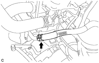
Connect the outlet heater water hose.
-
-
CONNECT INLET HEATER WATER HOSE
-
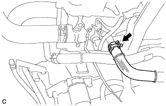
Connect the inlet heater water hose.
-
-
INSTALL THROTTLE BODY ASSEMBLY
-
INSPECT FOR FUEL LEAK
-
Check fuel pump operation.
-
Connect the intelligent tester to the DLC3.
-
Turn the engine switch on (IG) and turn the intelligent tester on.
Note
Do not start the engine.
-
Enter the following menus: Powertrain / Engine / Active Test / Control the Fuel Pump / Speed.
-
Check for pressure in the fuel inlet tube from the fuel line. Check that sounds of fuel flowing from the fuel tank can be heard. If no sounds can be heard, check the integration relay, fuel pump, ECM and wiring connectors.
-
-
Check for fuel leaks.
-
Check that there are no fuel leaks from the fuel system after doing any maintenance or repairs. If there is a fuel leak, repair or replace parts as necessary.
-
-
Turn the engine switch off.
-
Disconnect the intelligent tester from the DLC3.
-