FUEL INJECTOR INSTALLATION

-
INSTALL FUEL INJECTOR ASSEMBLY
-
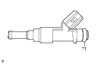
Text in Illustration *1 New O-ring Apply a light coat of spindle oil or gasoline to new O-rings, and install them to each injector.
-
Apply a light coat of spindle oil or gasoline where the fuel delivery pipe contacts each O-ring.
-
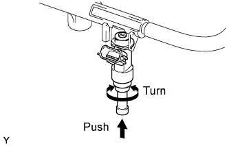
Push and twist each fuel injector to install them into the fuel delivery pipe.
-
Position each fuel injector connector outward.
Note
-
Be careful not to twist the O-rings.
-
After installing a fuel injector, check that it turns smoothly. If not, reinstall it with a new O-ring.
-
-
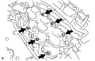
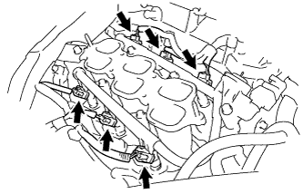
Install 6 new injector vibration insulators to the intake manifold.
-
Place the fuel delivery pipe with the 6 fuel injectors in position on the intake manifold.
Note
Be careful not to drop the fuel injectors when installing the fuel delivery pipe.
-
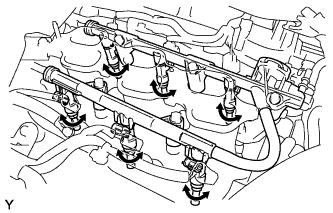
Temporarily install the 5 bolts which are used to hold the fuel delivery pipe to the intake manifold.
Note
After installing the fuel injectors, check that they turn smoothly. If not, reinstall the injectors with new O-rings.
-
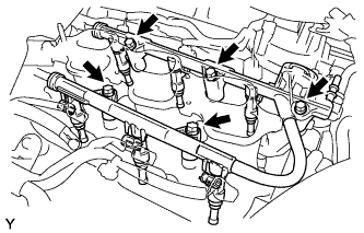
Tighten the 5 bolts which are used to hold the fuel delivery pipe to the intake manifold.
- Torque:
- 21 N*m { 214 kgf*cm, 15 ft.*lbf }
-
Connect the 6 fuel injector connectors.
-
-
CONNECT FUEL TUBE SUB-ASSEMBLY
-
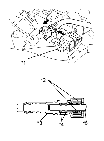
Text in Illustration *1 No. 2 Fuel Pipe Clamp *2 Retainer *3 Fuel Tube Connector *4 O-ring *5 Pipe Push in the tube connector onto the pipe until the tube connector makes a "click" sound.
Note
-
Before connecting the tube, make sure that it is not damaged. Make sure that there is no dirt present on the connecting surfaces.
-
After connecting, check that the fuel tube connector and the pipe are securely connected by pulling on them.
-
-
Install the No. 2 fuel pipe clamp.
-
-
INSTALL FUEL HOSE PROTECTOR
-
Install the fuel hose protector with the 2 bolts and nut.
- Torque:
- Bolt
- 21 N*m { 214 kgf*cm, 15 ft.*lbf }
- Nut
- 10 N*m { 102 kgf*cm, 7 ft.*lbf }
-
-
INSTALL INTAKE AIR SURGE TANK ASSEMBLY
Tech Tips
-
CONNECT CABLE TO NEGATIVE BATTERY TERMINAL
Note
When disconnecting the cable, some systems need to be initialized after the cable is reconnected Click here.
-
INSPECT FOR COOLANT LEAK
CAUTION:
Do not remove the radiator cap while the engine and radiator are still hot. Pressurized, hot engine coolant and steam may be released and cause serious burns.
Note
Before performing each inspection, turn the A/C switch off.
-
Remove the radiator cap.
-
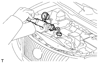
Fill the radiator with coolant and attach a radiator cap tester.
-
Warm up the engine.
-
Using the radiator cap tester, increase the pressure inside the radiator to 118 kPa (1.2 kgf/cm2, 17 psi), and check that the pressure does not drop.
If the pressure drops, check the hoses, radiator and water pump for leaks. If no external leaks are found, check the heater core, cylinder block and cylinder head.
-
Remove the radiator cap tester.
-
Install the radiator cap.
-
-
INSPECT FOR FUEL LEAK
Tech Tips