FUEL PRESSURE PULSATION DAMPER REMOVAL

-
PRECAUTION
Note
After turning the engine switch off, waiting time may be required before disconnecting the cable from the negative (-) battery terminal. Therefore, make sure to read the disconnecting the cable from the negative (-) battery terminal notice before proceeding with work Click here.
-
DISCHARGE FUEL SYSTEM PRESSURE
-
DISCONNECT CABLE FROM NEGATIVE BATTERY TERMINAL
Note
When disconnecting the cable, some systems need to be initialized after the cable is reconnected Click here.
-
REMOVE WINDSHIELD WIPER MOTOR AND LINK
-
REMOVE HOSE BRACKET (for LHD)
-
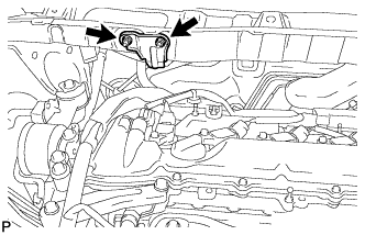
Remove the 2 nuts and separate the hose bracket from the outer cowl top panel sub-assembly.
-
-
REMOVE OUTER COWL TOP PANEL SUB-ASSEMBLY (for LHD)
-
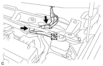
Disconnect the connector (w/ Windshield Deicer).
-
Disengage the grommet and clamp, and separate the wire harness.
-
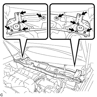
Remove the 6 nuts, 4 bolts and outer cowl top panel sub-assembly.
-
-
REMOVE OUTER COWL TOP PANEL SUB-ASSEMBLY (for RHD)
-
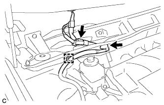
Disconnect the connector (w/ Windshield Deicer).
-
Disengage the grommet and clamp, and separate the wire harness.
-
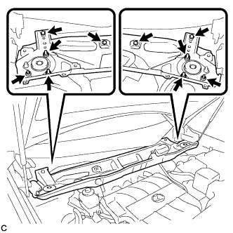
Remove the 6 nuts, 4 bolts and outer cowl top panel sub-assembly.
-
-
REMOVE NO. 1 ENGINE COVER SUB-ASSEMBLY
-
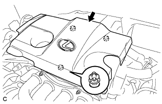
Lift the rear of the No. 1 engine cover sub-assembly to detach the cover from the 2 pins, and then lift the front of the No. 1 engine cover sub-assembly to detach the cover from the pin and remove the No. 1 engine cover sub-assembly.
Note
Attempting to disengage both front and rear clips at the same time may cause the No. 1 engine cover sub-assembly to break.
-
-
REMOVE AIR CLEANER ASSEMBLY
-
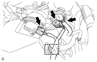
Disconnect the vacuum switching valve connector and fuel vapor feed hose.
-
Disconnect the mass air flow meter connector and separate the wire harness clamp from the air cleaner.
-
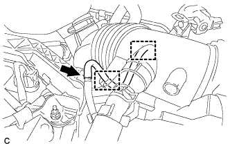
Disconnect the No. 2 fuel vapor feed hose from the vacuum switching valve and air cleaner hose.
-
Disconnect the vacuum switching valve connector and 2 wire harness clamps from the air cleaner.
-
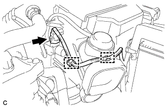
Disconnect the ventilation hose from the cylinder head cover.
-
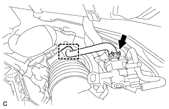
Disconnect the vacuum hose and separate it from the 2 hose clamps of the air cleaner hose.
-
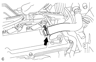
Loosen the bolt of the hose clamp and disconnect the air cleaner hose from the throttle body assembly.
-
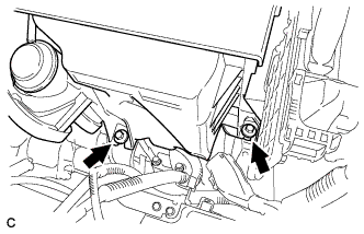
Remove the 2 bolts and move the air cleaner assembly upward to disengage and remove it from the throttle body assembly.
-
-
REMOVE FUEL TUBE SUB-ASSEMBLY
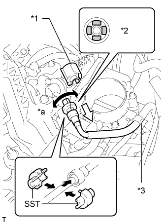
Text in Illustration *1 No. 2 Fuel Pipe Clamp *2 Retainer *3 Fuel Hose Clamp *a Turn Note
Do not forcibly bend, kink or twist the fuel tube.
-
Remove the fuel tube from the fuel hose clamp.
-
Remove the No. 2 fuel pipe clamp.
-
Wipe off any dirt on the fuel tube connector.
-
Hold the fuel tube connector, and then install SST.
- SST
- 09268-21011
-
Turn SST to align the retainer inside the fuel tube connector with the chamfered part of SST.
-
Insert SST into the fuel tube and hold it. Then push the fuel tube connector toward SST.
-
Mount the retainer of the fuel tube connector onto the chamfered part of SST.
-
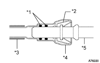
Text in Illustration *1 O-ring *2 Retainer *3 Nylon Tube *4 Housing *5 Pipe Slide SST and the fuel tube connector together toward the fuel tube until they make a "click" sound, and then disconnect the fuel tube.
Note
-
Check for foreign matter in the fuel tube around the fuel tube connector. Clean it if necessary. Foreign matter can affect the ability of the O-rings to seal the connector and fuel pipe.
-
Do not use any tools to separate the connector and pipe.
-
Do not forcefully bend, kink or twist the hose.
-
Keep the connector and pipe free from foreign matter.
-
If the connector and pipe are stuck together, pinch the connector and turn it carefully to disconnect it.
-
Put the connector in a plastic bag to prevent damage and contamination.
-
-
-
REMOVE FUEL PRESSURE PULSATION DAMPER ASSEMBLY
-
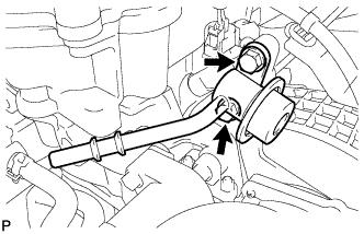
Remove the 2 bolts and fuel pressure pulsation damper.
-
Remove the O-ring from the fuel pressure pulsation damper.
-