ENGINE ASSEMBLY REMOVAL

-
PRECAUTION (w/ Air Suspension)
Note
Be sure to read Precaution thoroughly before servicing ( Click here).
-
PRECAUTION (w/ Navigation System for HDD)
Note
After the engine switch is turned off, the display and navigation module display (HDD navigation system) records various types of memory and settings. As a result, after turning the engine switch off, make sure to wait for the time specified in the following table before disconnecting the cable from the negative (-) battery terminal.
Waiting Time before Disconnecting Cable from Negative (-) Battery Terminal Specification Waiting Time w/o Telematics transceiver 60 sec. w/ Telematics transceiver 120 sec. -
ALIGN FRONT WHEELS FACING STRAIGHT AHEAD
-
REMOVE ENGINE ROOM SIDE COVER
-
Remove the 4 clips.
-
Disengage the guide and remove the engine room side cover.
-
-
REMOVE ENGINE ROOM SIDE COVER LH
-
Remove the 4 clips.
-
Disengage the guide and remove the engine room side cover LH.
-
-
REMOVE COOL AIR INTAKE DUCT SEAL
-
Remove the 6 clips and cool air intake duct seal.
-
-
RECOVER REFRIGERANT FROM REFRIGERATION SYSTEM
-
Start up the engine.
-
Turn the A/C switch on.
-
Operate the cooler compressor at an engine speed of approximately 1000 rpm for 5 to 6 minutes to circulate the refrigerant. This causes most of the compressor oil from the various components of the A/C system to collect in the A/C compressor.
-
Stop the engine.
-
Recover the refrigerant from the A/C system using a refrigerant recovery unit.
-
-
DISCHARGE FUEL SYSTEM PRESSURE
Tech Tips
-
DISCONNECT CABLE FROM NEGATIVE BATTERY TERMINAL
CAUTION:
When disconnecting the cable, some systems need to be initialized after the cable is reconnected Click here.
-
REMOVE FRONT WHEEL
-
REMOVE NO. 1 ENGINE UNDER COVER
-
REMOVE NO. 2 ENGINE UNDER COVER
-
REMOVE FRONT FLOOR COVER LH
-
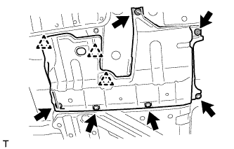
Disconnect the 3 clips.
-
Remove the 2 screws, 4 bolts and front floor cover LH.
-
-
REMOVE FRONT FENDER LINER LH
-
REMOVE FRONT FENDER LINER RH
-
REMOVE FRONT FENDER APRON SEAL LH
-
Remove the 2 bolts, clip and front fender apron seal LH.
-
-
REMOVE FRONT FENDER APRON SEAL RH
-
Remove the 2 bolts, clip and front fender apron seal RH.
-
-
REMOVE SUSPENSION TOWER DAMPER (w/ Suspension Tower Damper)
-
Remove the 4 nuts and the suspension tower damper from the vehicle.
-
-
DRAIN ENGINE OIL
-
Remove the oil filler cap.
-
Remove the oil pan drain plug and gasket, and drain the oil into a container.
-
Clean the oil pan drain plug.
-
Install the oil pan drain plug with a new gasket.
- Torque:
- 40 N*m { 408 kgf*cm, 30 ft.*lbf }
-
-
DRAIN ENGINE COOLANT
CAUTION:
Do not remove the radiator cap sub-assembly, cylinder block drain cock plugs or radiator drain cock plug while the engine and radiator assembly are still hot. Pressurized, hot engine coolant and steam may be released and cause serious burns.
-
Loosen the radiator drain cock plug.
-
Loosen the cylinder block drain cock plug. (for Bank 1)
-
Loosen the cylinder block drain cock plug. (for Bank 2, w/ Cylinder Block Drain Cock Plug)
-
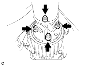
Remove the radiator cap sub-assembly.
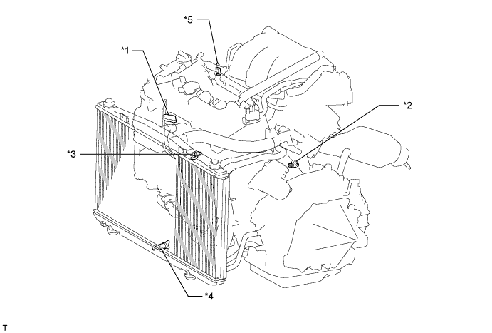
Text in Illustration *1 Radiator Cap Sub-assembly *2 Cylinder Block Drain Cock Plug (for Bank 1) *3 Cylinder Block Drain Cock Plug (for Bank 2, w/ Cylinder Block Drain Cock Plug) *4 Radiator Drain Cock Plug *5 Air Drain Cock Plug - - Tech Tips
Collect the engine coolant in a container and dispose of it according to the regulations in your area.
-
-
DRAIN AUTOMATIC TRANSAXLE FLUID
-
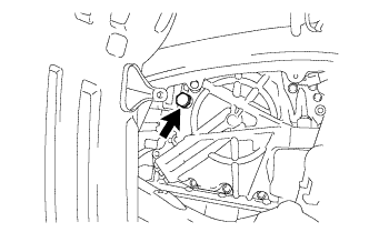
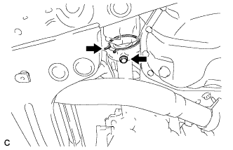
Remove the refill plug and gasket from the automatic transaxle.
-
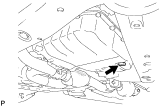
Using a 6 mm hexagon socket wrench, remove the overflow plug and gasket from the automatic transaxle.
-
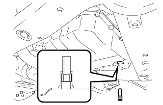
Using a 6 mm hexagon socket wrench, remove the No. 1 transmission oil filler tube from the automatic transaxle.
-
Drain automatic transaxle fluid from the automatic transaxle.
-
Using a 6 mm hexagon socket wrench, install the No. 1 transmission oil filler tube to the automatic transaxle.
- Torque:
- 1.7 N*m { 17 kgf*cm, 15 in.*lbf }
-
Using a 6 mm hexagon socket wrench, install a new gasket and the overflow plug to the automatic transaxle.
- Torque:
- 40 N*m { 408 kgf*cm, 30 ft.*lbf }
-
Temporarily install the gasket and the refill plug to the automatic transaxle.
-
-
DRAIN TRANSFER OIL
-
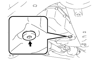
Remove the transfer drain plug and gasket to drain the transfer oil.
-
Install a new gasket and the transfer drain plug.
- Torque:
- 49 N*m { 500 kgf*cm, 36 ft.*lbf }
-
-
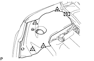
REMOVE FRONT FENDER TOP REINFORCEMENT SUB-ASSEMBLY LH
-
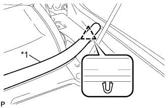
Text in Illustration *1 Hood to Cowl Top Seal Disengage the clip and the hood to cowl top seal to the front fender top reinforcement sub-assembly LH.
-
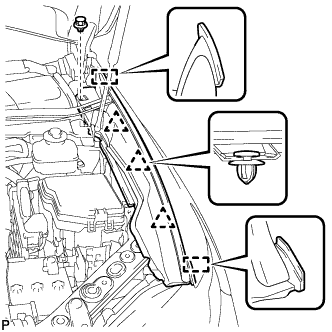
Remove the clip.
-
Disengage the 3 clips and 2 guides, and remove the front fender top reinforcement sub-assembly LH.
-
-
REMOVE FRONT FENDER TOP REINFORCEMENT SUB-ASSEMBLY RH
Tech Tips
Use the same procedure for the RH side and LH side.
-
REMOVE FRONT FENDER TO COWL SIDE SEAL LH
-
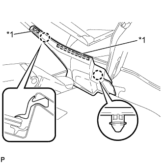
Text in Illustration *1 Double-Sided Tape Disengage the 2 claws and remove the front fender to cowl side seal LH.
-
-
REMOVE FRONT FENDER TO COWL SIDE SEAL RH
Tech Tips
Use the same procedure for the RH side and LH side.
-
REMOVE FRONT WIPER ARM HEAD CAP
-
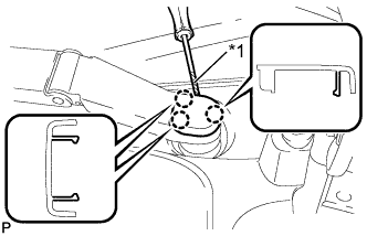
Text in Illustration *1 Protective Tape Using a screwdriver, disengage the 3 claws and remove the front wiper arm head cap.
Tech Tips
Tape the screwdriver tip before use.
-
-
REMOVE FRONT WIPER ARM AND BLADE ASSEMBLY LH
-
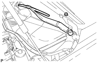
Remove the nut and the front wiper arm and blade assembly LH.
-
-
REMOVE FRONT WIPER ARM AND BLADE ASSEMBLY RH
-
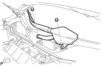
Remove the 2 nuts and the front wiper arm and blade assembly RH.
-
-
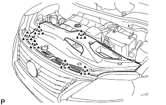
REMOVE COWL TOP VENTILATOR LOUVER SUB-ASSEMBLY
-
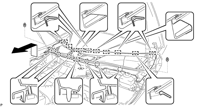
Remove the 2 clips.
-
Disengage the 6 claws and guide <A>.
-
Disengage the 10 guides and pull out the cowl top ventilator louver sub-assembly as shown in the illustration.
-
-
REMOVE WINDSHIELD WIPER MOTOR AND LINK ASSEMBLY
-
Operate the wiper and stop the windshield wiper motor at the automatic stop position.
-
w/o Deicer:
-
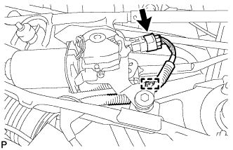
Disconnect the connector.
-
Disengage the clamp.
-
-
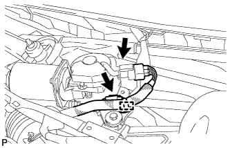
w/ Deicer:
-
Disconnect the 2 connectors.
-
Disengage the clamp.
-
-
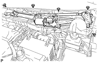
Remove the 5 bolts and the wind shield wiper motor and link assembly as shown in the illustration.
Note
Be careful not to damage the windshield when removing the windshield wiper motor and link assembly.
-
-
REMOVE FRONT SHOCK ABSORBER CAP (w/ Air Suspension)
-
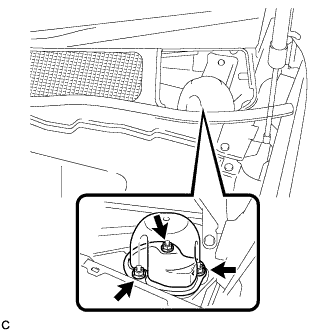
Remove the 3 nuts and the front shock absorber cap.
-
-
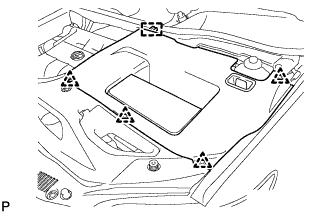
REMOVE OUTER COWL TOP PANEL SUB-ASSEMBLY (for LHD)
-
Disconnect the connector (w/ Windshield Deicer).
-
Disengage the grommet and clamp, and separate the wire harness.
-
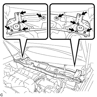
Remove the 6 nuts, 4 bolts and outer cowl top panel sub-assembly.
-
-
REMOVE OUTER COWL TOP PANEL SUB-ASSEMBLY (for RHD)
-
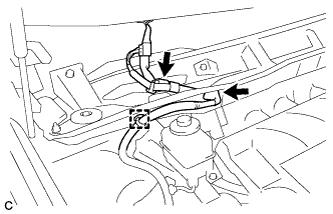
Disconnect the connector (w/ Windshield Deicer).
-
Disengage the grommet and clamp, and separate the wire harness.
-
Remove the 6 nuts, 4 bolts and outer cowl top panel sub-assembly.
-
-
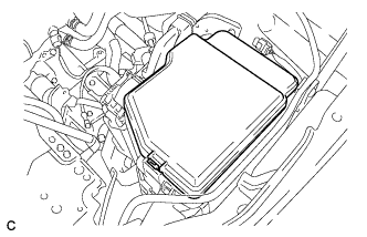
REMOVE V-BANK COVER SUB-ASSEMBLY
-
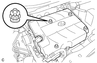
Hold the front of the V-bank cover sub-assembly and raise it to disengage the 2 retainers on the front of the V-bank cover sub-assembly. Continue to raise the V-bank cover sub-assembly to disengage the 2 retainers on the rear of the V-bank cover sub-assembly and remove the V-bank cover sub-assembly.
Note
Attempting to disengage both front and rear retainers at the same time may cause the V-bank cover sub-assembly to break.
-
-
REMOVE NO. 2 AIR CLEANER INLET
-
Disconnect the 2 vacuum hose clamps from the No. 2 air cleaner inlet.
-
Remove the 2 bolts and No. 2 air cleaner inlet.
-
-
REMOVE NO. 1 AIR CLEANER INLET
-
Disconnect the vacuum hose clamp from the No. 1 air cleaner inlet.
-
Remove the bolt and No. 1 air cleaner inlet.
-
-
REMOVE BATTERY
-
Disconnect the positive (+) cable from the positive (+) battery terminal.
-
Loosen the nut, and remove the bolt from the battery clamp.
-
Remove the battery and battery tray.
-
-
REMOVE AIR CLEANER ASSEMBLY
-
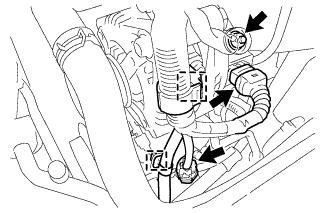
Separate the mass air flow meter connector and wire harness clamp.
-
Separate the vacuum hose from the intake air surge tank assembly.
-
Separate the vacuum hose from the hose clamp.
-
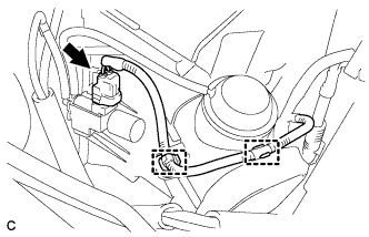
Separate the vacuum switching valve connector and 2 wire harness clamps.
-
Separate the 2 vacuum hoses.
-
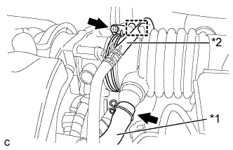
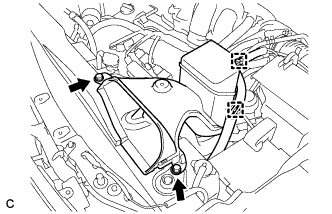
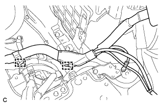
Text in Illustration *1 Ventilation Hose *2 Fuel Vapor Feed Hose Separate the ventilation hose and the fuel vapor feed hose.
-
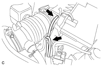
Loosen the hose clamp and separate the air cleaner hose from the throttle body.
-
Remove the 2 bolts and remove the air cleaner assembly.
-
-
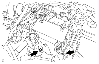
REMOVE AIR CLEANER BRACKET
-
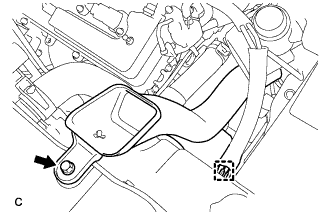
Disconnect the engine wire clamp.
-
Remove the 2 bolts and air cleaner bracket.
-
-
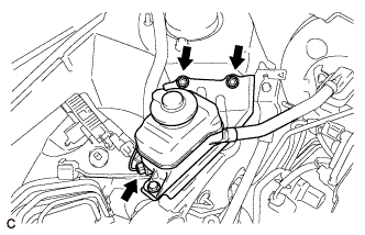
SEPARATE BRAKE MASTER CYLINDER RESERVOIR SUB-ASSEMBLY (for LHD)
-
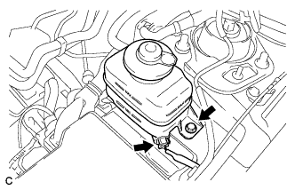
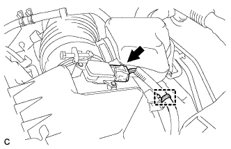
Disconnect the connector from the brake master cylinder reservoir sub-assembly.
-
Remove the bolt and separate the radiator reservoir tank assembly from the reservoir bracket.
-
-
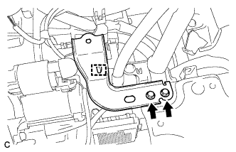
REMOVE RESERVOIR BRACKET (for LHD)
-
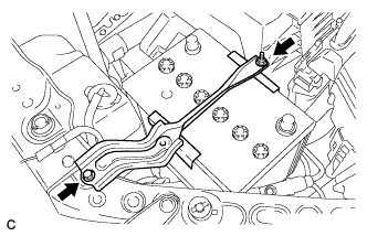
Remove the 2 bolts and reservoir bracket.
-
-
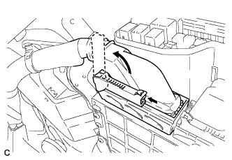
REMOVE NO. 1 RELAY BLOCK COVER
-
Remove the No. 1 relay block cover.
-
-
DISCONNECT ENGINE WIRE
-
Remove the 2 bolts and separate the 2 earth wires.
-
Disconnect the 2 wire clamps.
-
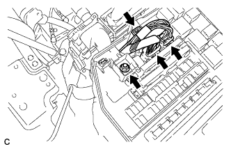
Disconnect the 3 connectors.
-
Remove the nut.
-
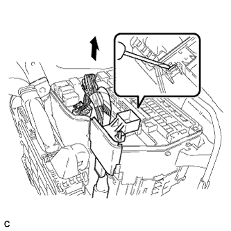
Using a screwdriver, unlock the claw and separate the engine wire from the engine room relay block.
-
Pull up the lever to disconnect the ECM connector.
-
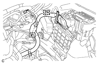
Disconnect the 2 wire clamps.
-
-
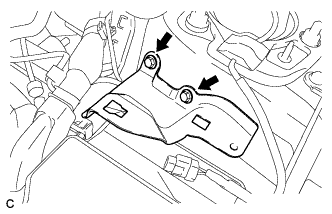
SEPARATE BRAKE MASTER CYLINDER RESERVOIR SUB-ASSEMBLY (for RHD)
-
Disconnect the connector.
-
Remove the 2 bolts and separate the brake master cylinder reservoir sub-assembly from the body.
-
-
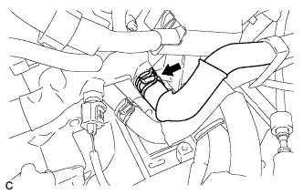
DISCONNECT TRANSMISSION CONTROL CABLE ASSEMBLY
-
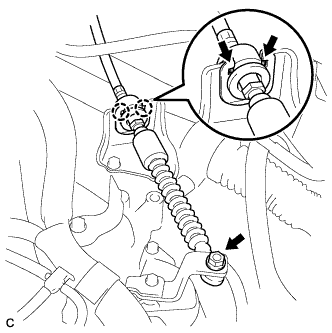
Remove the nut from the control shaft lever.
-
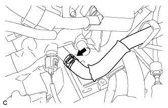
Using a screwdriver, disengage the 4 claws and disconnect the control cable with clip from the control cable bracket.
-
Remove the clip.
-
-
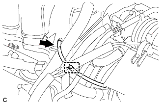
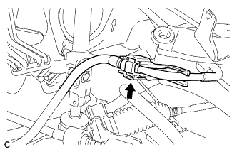
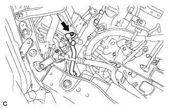
DISCONNECT NO. 1 FUEL VAPOR FEED HOSE
-
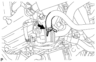
Disconnect the No. 1 fuel vapor feed hose.
-
-
DISCONNECT NO. 1 RADIATOR HOSE
-
Disconnect the No. 1 radiator hose.
-
Separate the No. 1 radiator hose from the radiator pipe clamp.
-
-
DISCONNECT NO. 2 RADIATOR HOSE
-
Disconnect the No. 2 radiator hose.
-
-
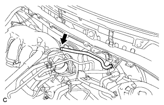
DISCONNECT INLET HEATER WATER HOSE
-
Disconnect the inlet heater water hose.
-
-
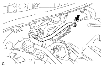
DISCONNECT OUTLET HEATER WATER HOSE
-
Disconnect the outlet heater water hose.
-
-
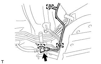
DISCONNECT FUEL MAIN TUBE
-
Remove the No. 1 fuel pipe clamp.
-
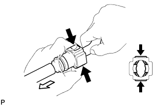
Disconnect the connector from the pipe by hand. When the connector and the pipe are stuck, push in and pull on the connector to release it. Pull the connector out of the pipe carefully.
Note
-
Check for any dirt and foreign matter contamination in the pipe and around the connector. Clean if necessary. Foreign matter may damage the O-rings or cause leaks in the seal between the pipe and connector.
-
Do not use any tools to separate the pipe and connector.
-
Do not forcefully bend or twist the nylon tube.
-
Check for any dirt and foreign matter on the pipe seal surface. Clean if necessary.
-
Put the pipe and connector ends in plastic bags to prevent damage and dirt contamination.
-
If the pipe and connector are stuck together, pinch the tube between your fingers and turn it carefully to free it. Then disconnect the hose.
-
-
-
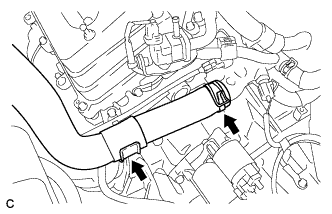
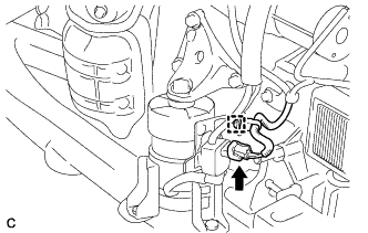
DISCONNECT NO. 1 OUTLET OIL COOLER HOSE
-
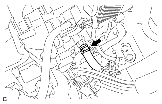
Disconnect the No. 1 outlet oil cooler hose.
-
-
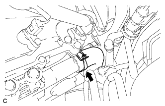
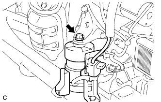
DISCONNECT NO. 1 INLET OIL COOLER HOSE
-
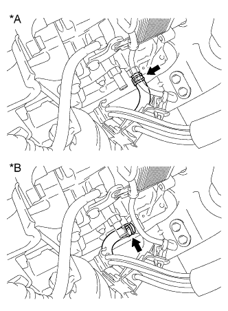
Text in Illustration *A for Straight Type *B for Elbow Type Disconnect the No. 1 inlet oil cooler hose.
-
-
DISCONNECT UNION TO CHECK VALVE HOSE (for LHD)
-
Disconnect the union to check valve hose.
-
-
REMOVE UNION TO CHECK VALVE HOSE (for RHD)
-
Disconnect the union to check valve hose.
-
-
REMOVE NO. 2 ENGINE MOUNTING STAY RH
-
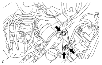
Remove the bolt, 2 nuts and No. 2 engine mounting stay RH.
-
-
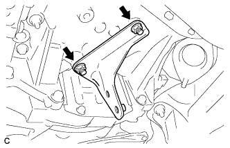
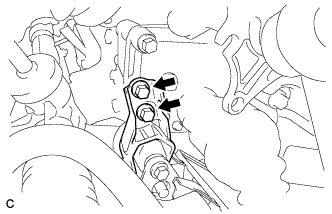
REMOVE ENGINE MOVING CONTROL ROD BRACKET
-
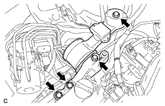
Remove the 4 bolts and engine moving control rod bracket with engine moving control rod.
-
-
REMOVE NO. 3 ENGINE MOUNTING STAY RH
Tech Tips
Perform this procedure only when replacement of the engine moving control rod or No. 3 engine moving stay RH is necessary.
-
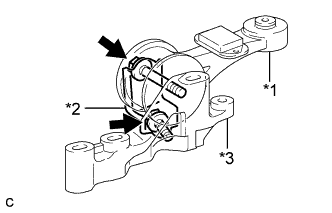
Text in Illustration *1 Engine moving control rod *2 No. 3 engine moving stay RH *3 Engine moving control rod bracket Remove the 2 bolts, engine moving control rod and No. 3 engine moving stay RH from the engine moving control rod bracket.
-
-
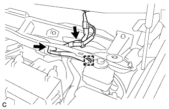
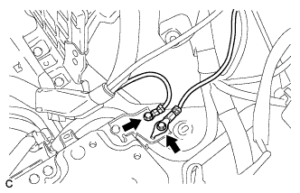
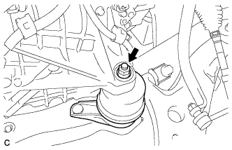
DISCONNECT DISCHARGE HOSE SUB-ASSEMBLY
-
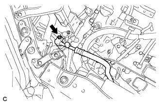
Remove the nut and disconnect the discharge hose sub-assembly.
Note
Seal the openings of the disconnected parts using vinyl tape to prevent entry of moisture and foreign matter.
-
-
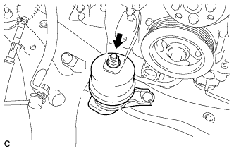
DISCONNECT SUCTION HOSE SUB-ASSEMBLY
-
Remove the nut and disconnect the suction hose sub-assembly.
Note
Seal the openings of the disconnected parts using vinyl tape to prevent entry of moisture and foreign matter.
-
-
REMOVE FRONT NO. 3 EXHAUST PIPE SUB-ASSEMBLY
-
Disconnect the 3 clamps and oxygen sensor connector (for Bank 1 Sensor 2).
-
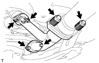
Remove the 4 bolts, 2 nuts, 2 compression springs and No. 3 exhaust pipe sub-assembly.
-
Remove the 3 gaskets from the No. 3 exhaust pipe sub-assembly.
-
-
REMOVE FRONT EXHAUST PIPE ASSEMBLY
-
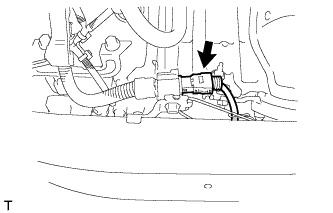
Disconnect the No. 2 oxygen sensor connector (for Bank 2 Sensor 2).
-
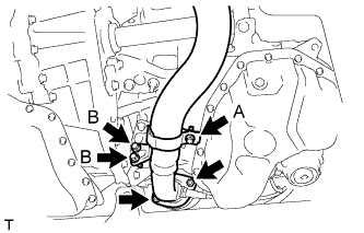
Loosen the bolt (A).
-
Remove the 2 bolts (B), 2 nuts and front exhaust pipe assembly.
-
Remove the gasket from the front exhaust pipe assembly.
-
-
REMOVE NO. 1 EXHAUST PIPE SUPPORT BRACKET
-
Remove the 2 nuts and No. 1 exhaust pipe support bracket.
-
-
REMOVE PROPELLER WITH CENTER BEARING SHAFT ASSEMBLY
-
Depress the brake pedal and hold it.
-
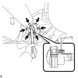
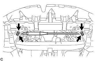
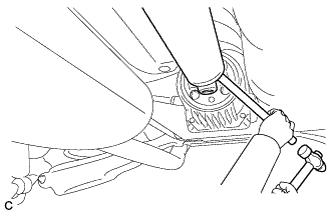
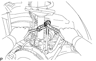
Text in Illustration *1 Piece of Cloth Using a hexagon wrench (6 mm), loosen the cross groove joint set bolts 1/2 turn.
Note
-
Put a piece of cloth or equivalent into the inside of the universal joint cover so that the boot does not touch the inside of the universal joint cover.
-
Do not remove the bolts.
-
-
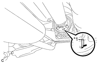
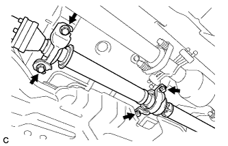
Text in Illustration *1 Matchmark Place matchmarks on the rear propeller shaft and rear drive pinion flange sub-assembly.
-
Remove the 4 nuts, 4 bolts and 4 washers.
-
Using a brass bar and a hammer, remove the propeller with center bearing shaft assembly.
-
Remove the 4 bolts and 4 No. 2 center support bearing washers.
Note
When removing the bolts and washers, do not apply excessive force to the universal joint.
-
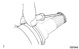
Pull out the propeller with center bearing shaft assembly from the transfer.
Note
-
When removing the propeller shaft, do not apply excessive force to the universal joint.
-
During and after the removal of the propeller shaft, keep the universal joint angle straight (within 15 degrees).
-
Be careful not to damage the oil seal.
-
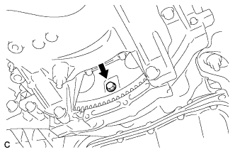
-
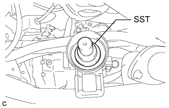
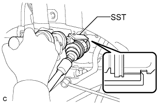
Insert SST into the transfer to prevent oil leakage.
- SST
- 09325-20010
Note
Be careful not to damage the oil seal.
-
-
SECURE STEERING WHEEL
-
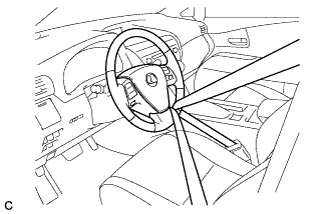
Secure the steering wheel with the seat belt in order to prevent it from rotating.
Tech Tips
This operation is necessary to prevent damage to the spiral cable.
-
-
SEPARATE STEERING INTERMEDIATE SHAFT ASSEMBLY
-
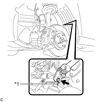
Text in Illustration *1 Matchmark Put matchmarks on the steering intermediate shaft assembly and power steering link assembly.
Note
Do not separate the steering intermediate shaft assembly from the power steering link assembly.
-
Remove the bolt.
-
Separate the steering intermediate shaft assembly from the power steering link assembly.
-
-
SEPARATE HEIGHT CONTROL SENSOR LINK SUB-ASSEMBLY LH (w/ Air Suspension)
-
Remove the nut and separate the height control sensor link sub-assembly LH from the front lower suspension arm LH.
-
-
SEPARATE HEIGHT CONTROL SENSOR LINK SUB-ASSEMBLY RH (w/ Air Suspension)
Tech Tips
Perform the same procedure as for the LH side.
-
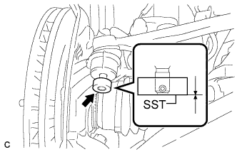
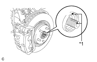
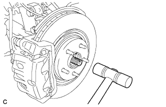
REMOVE FRONT AXLE SHAFT NUT LH
-
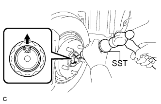
Using SST and a hammer, release the staked part of the front axle shaft nut.
- SST
- 09930-00010
Note
Loosen the staked part of the nut completely, otherwise the threads of the drive shaft may be damaged.
-
While applying the brakes, remove the front axle shaft nut.
-
-
REMOVE FRONT AXLE SHAFT NUT RH
Tech Tips
Perform the same procedure as for the LH side.
-
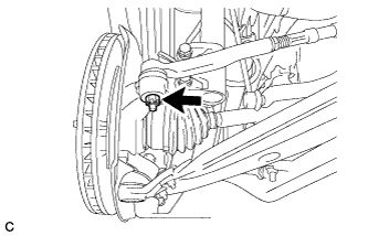
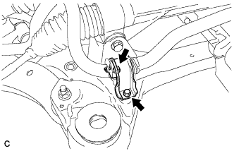
SEPARATE FRONT STABILIZER LINK ASSEMBLY LH
-
Remove the nut and separate the front stabilizer link assembly from the front shock absorber.
Tech Tips
If the ball joint turns together with the nut, use a hexagon wrench (6 mm) to hold the stud bolt.
-
-
SEPARATE FRONT STABILIZER LINK ASSEMBLY RH
Tech Tips
Perform the same procedure as for the LH side.
-
SEPARATE FRONT SPEED SENSOR LH
-
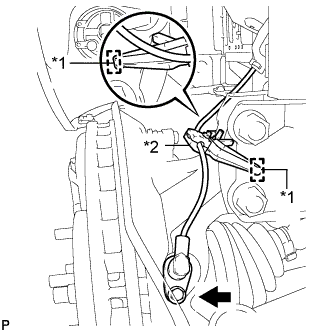
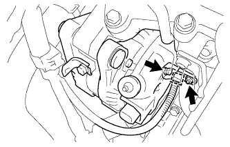
Text in Illustration *1 Hole *2 Resin Clamp Remove the bolt and resin clamp, and separate the front speed sensor.
Note
-
Be sure to completely separate the front speed sensor from the front shock absorber with coil spring.
-
Be careful not to damage the front speed sensor.
-
Clean the speed sensor installation hole and the surfaces every time the speed sensor is removed.
-
-
-
SEPARATE FRONT SPEED SENSOR RH
Tech Tips
Perform the same procedure as for the LH side.
-
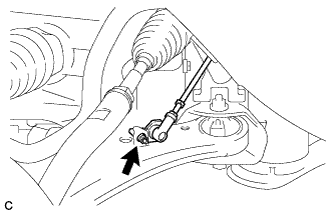
SEPARATE TIE ROD ASSEMBLY LH
-
Remove the cotter pin and nut.
-
Install SST to the tie rod end.
- SST
- 09960-20010 ( 09961-02060 )
Note
Make sure that the upper ends of the tie rod end and SST are aligned.
-
Using SST, separate the tie rod end from the steering knuckle.
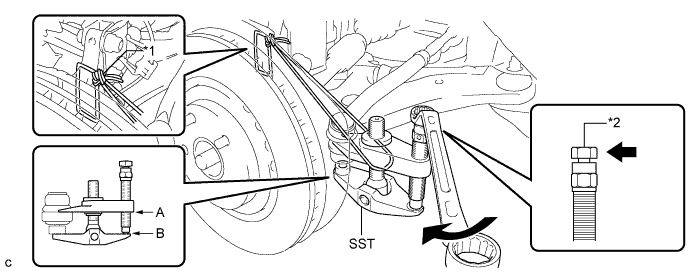
Text in Illustration *1 Tie the string without allowing for any slack. *2 Place the wrench here. - SST
- 09960-20010 ( 09961-02010 )
Note
-
When securing SST to the steering knuckle, be sure to tighten SST using a string to prevent it from falling.
-
Install SST so that A and B are parallel.
-
Be sure to place a wrench on the part indicated in the illustration.
-
Do not damage the front disc brake dust cover.
-
Do not damage the ball joint dust cover.
-
Do not damage the steering knuckle.
-
-
SEPARATE TIE ROD ASSEMBLY RH
Tech Tips
Perform the same procedure as for the LH side.
-
SEPARATE FRONT LOWER SUSPENSION ARM LH
-
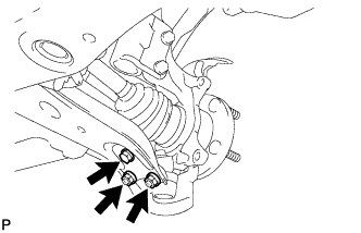
Remove the bolt and 2 nuts, and separate the front lower suspension arm from the lower ball joint.
-
-
SEPARATE FRONT LOWER SUSPENSION ARM RH
Tech Tips
Perform the same procedure as for the LH side.
-
SEPARATE FRONT DRIVE SHAFT ASSEMBLY
-
Text in Illustration *1 Matchmark Put matchmarks on the front drive shaft assembly and the front axle hub sub-assembly.
-
Using a plastic hammer, separate the front drive shaft assembly from the front axle assembly.
Note
Loosen the staked part of the front axle hub nut completely, otherwise the threads of the drive shaft may be damaged.
-
-
REMOVE FRONT DRIVE SHAFT ASSEMBLY LH
-
Using SST, remove the front drive shaft assembly LH.
- SST
- 09520-00031
- 09520-01010
Note
-
Be careful not to damage the drive shaft dust cover, boot or oil seal.
-
Be careful not to drop the drive shaft assembly.
-
-
REMOVE FRONT DRIVE SHAFT HOLE SNAP RING
-
Using a screwdriver, remove the front drive shaft hole snap ring.
-
-
REMOVE FRONT DRIVE SHAFT ASSEMBLY RH
-
Remove the bearing bracket hole snap ring from the drive shaft bearing bracket.
-
Remove the bolt and front drive shaft assembly RH from the drive shaft bearing bracket.
Note
Do not damage the boot or oil seal.
-
-
REMOVE FLYWHEEL HOUSING UNDER COVER
-
Remove the 2 bolts and flywheel housing under cover.
-
-
REMOVE DRIVE PLATE AND TORQUE CONVERTER ASSEMBLY SETTING BOLT
-
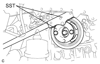
Using SST, hold the crankshaft pulley.
- SST
- 09213-70011 ( 09213-70020 )
- 09330-00021
-
Remove the 6 drive plate and torque converter assembly setting bolts.
Tech Tips
There will be one black colored bolt.
-
-
REMOVE ENGINE ASSEMBLY WITH TRANSAXLE
-
Set the engine lifter.
Note
-
Install a height adjustment attachment and plate lift attachment onto the engine assembly with transaxle.
-
Securely support the engine assembly to prevent it from turning upside down until it is secured to an engine stand.
-
Do not perform any procedure while the engine assembly is suspended because doing so may cause the engine assembly to drop, resulting in injury. However, the engine assembly needs to be suspended when it is installed to or removed from an engine stand.
-
-
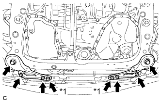
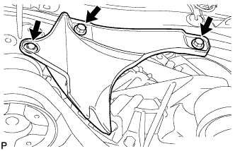
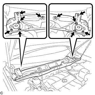
Text in Illustration *1 Nut Remove the 6 bolts, 2 nuts and frame side rail plates RH and LH.
-
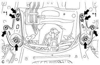
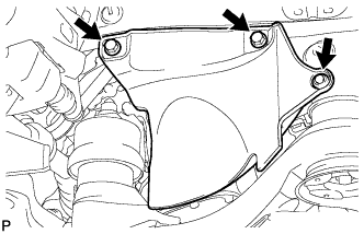
Text in Illustration *1 Nut Remove the 6 bolts, 2 nuts and front suspension member rear braces RH and LH.
-
Operate the engine lifter, then remove the engine assembly from the vehicle.
Note
-
Make sure that the engine is clear of all wiring and hoses.
-
While lowering the engine from the vehicle, do not allow it to contact the vehicle.
-
-
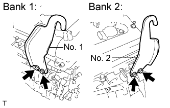
Install the No. 1 and No. 2 engine hangers with the 4 bolts.
- Torque:
- 33 N*m { 337 kgf*cm, 24 ft.*lbf }
Part No. Item Part No. No. 1 engine hanger 12281-31120 No. 2 engine hanger 12282-31100 Bolt 91671-10825 -
Attach the sling device to the engine hangers and chain block.
-
-
REMOVE V-RIBBED BELT
-
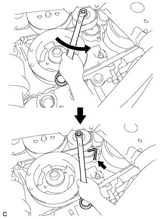
Release the V-ribbed belt tension by turning the V-ribbed belt tensioner counterclockwise, and remove the V-ribbed belt from the V-ribbed belt tensioner.
-
While turning the V-ribbed belt tensioner counterclockwise, align with its holes, and then insert a 5 mm bi-hexagon wrench into the holes to fix the V-ribbed belt tensioner.
-
-
REMOVE GENERATOR ASSEMBLY
-
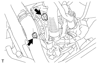
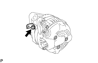
Turn back the terminal cap.
-
Remove the nut and disconnect the generator wire from terminal B.
-
Disconnect the generator connector from the generator assembly.
-
Disconnect the connector from the compressor and magnetic clutch.
-
Disconnect the wire harness clamps.
-
Remove the bolt and nut from the cylinder block.
-
Disconnect the wire harness clamp and remove the generator bracket.
-
Remove the 2 bolts.
-
Remove the bolt and the wire harness clamp stay.
-
-
REMOVE COMPRESSOR AND MAGNETIC CLUTCH
-
Disengage each clamp.
-
Disconnect each connector.
-
for Standard Bolt:
-
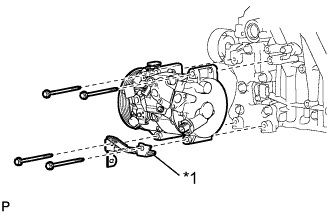
Text in Illustration *1 Bracket Remove the 4 bolts, bracket and the compressor and magnetic clutch.
-
-
for Stud Bolt:
-

Text in Illustration *1 Bracket *2 Nut *3 Stud bolt *4 Bolt Remove the 2 nuts, 2 bolts and bracket.
-
Remove the 2 stud bolts and the compressor and magnetic clutch.
-
-
-
REMOVE STARTER ASSEMBLY
-
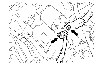
Disconnect the starter connector.
-
Turn back the terminal cap, remove the nut and disconnect the starter wire.
-
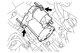
Remove the 2 bolts and starter.
-
-
REMOVE RADIATOR PIPE CLAMP
-
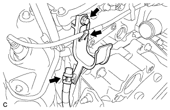
Separate the breather plug hose and sensor wire from the radiator pipe clamp.
-
Remove the bolt and radiator pipe clamp.
-
-
REMOVE ENGINE WIRE
-
Remove the engine wire from the engine with transaxle.
-
-
REMOVE FRONT NO. 1 STABILIZER BRACKET LH
-
Remove the 2 bolts and the front No. 1 stabilizer bracket LH from the front frame assembly.
-
-
REMOVE FRONT NO. 1 STABILIZER BRACKET RH
Tech Tips
Perform the same procedure as for the LH side.
-
REMOVE FRONT STABILIZER BAR
-
REMOVE STEERING LINK ASSEMBLY
-
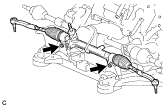
Remove the 2 bolts, 2 nuts and steering link assembly.
Note
Because the nut has its own stopper, do not turn the nut. Loosen the bolt with the nut secured.
-
-
REMOVE FRONT FRAME ASSEMBLY
-
Remove the nut and separate the engine mounting insulator LH.
-
Disconnect the wire clamp and connector.
-
Remove the bolt and separate the front engine mounting insulator.
-
Remove the nut and separate the engine mounting insulator RH.
-
Remove the 2 bolts and separate the rear engine mounting insulator assembly.
Note
Do not remove the rear engine mounting insulator assembly through bolts. Doing so makes it difficult to install the rear engine mounting insulator assembly.
-
Remove the front frame assembly.
-
-
REMOVE FRONT ENGINE MOUNTING INSULATOR
-
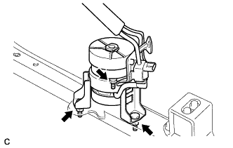
Remove the 2 hole plugs.
-
Remove the 3 nuts and front engine mounting insulator.
Tech Tips
Perform this procedure only when replacement of the front engine mounting insulator is necessary.
-
-
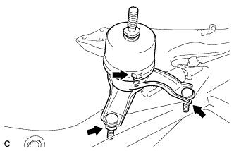
REMOVE ENGINE MOUNTING INSULATOR LH
-
Remove the 2 hole plugs.
-
Remove the 3 nuts and engine mounting insulator LH.
Tech Tips
Perform this procedure only when replacement of the engine mounting insulator LH is necessary.
-
-
REMOVE ENGINE MOUNTING INSULATOR RH
-
Remove the 2 hole plugs.
-
Remove the 3 nuts and engine mounting insulator RH.
Tech Tips
Perform this procedure only when replacement of the engine mounting insulator RH is necessary.
-
-
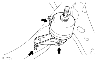
REMOVE REAR ENGINE MOUNTING INSULATOR ASSEMBLY
-
Remove the 2 hole plugs.
-
Remove the 2 nuts and rear engine mounting insulator assembly.
Note
Do not remove the rear engine mounting insulator assembly through bolts. Doing so makes it difficult to install the rear engine mounting insulator assembly.
Tech Tips
Perform this procedure only when replacement of the engine mounting insulator assembly is necessary.
-
-
REMOVE MANIFOLD STAY
-
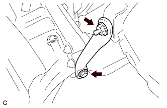
Remove the bolt, nut and manifold stay.
-
-
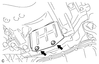
REMOVE TRANSFER STIFFENER PLATE RH
-
Remove the 4 bolts and transfer stiffener plate RH.
-
-
REMOVE AUTOMATIC TRANSAXLE ASSEMBLY
-
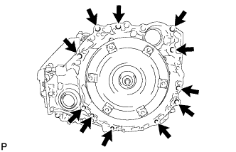
Remove the 11 bolts and transaxle.
Note
To prevent damage to the knock pins, do not pry between the transaxle and engine.
-
-
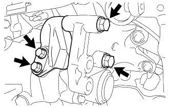
REMOVE ENGINE MOUNTING BRACKET RH
-
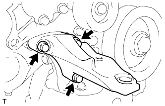
Remove the 3 bolts and engine mounting bracket RH.
-
-
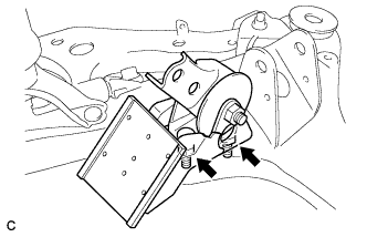
REMOVE REAR ENGINE MOUNTING BRACKET
-
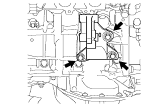
Remove the 3 bolts and rear engine mounting bracket.
-
-
REMOVE DRIVE PLATE AND RING GEAR SUB-ASSEMBLY
-
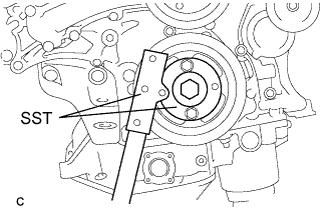
Using SST, hold the crankshaft pulley.
- SST
- 09213-70011 ( 09213-70020 )
- 09330-00021
-
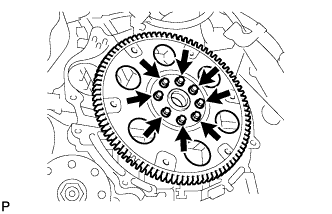
Remove the 8 bolts, front drive plate spacer, drive plate and ring gear sub-assembly and rear drive plate spacer.
-