- Click here
INSTALL CYLINDER HEAD GASKET RH
-
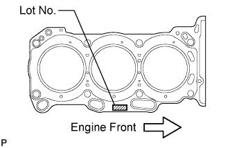
Place a new cylinder head gasket RH on the cylinder block surface with the Lot No. stamp upward.
Note:
-
Be careful of the installation direction.
-
Gently lower the cylinder head in order not to damage the gasket with the bottom part of the head.
-
-
- Click here
INSTALL CYLINDER HEAD SUB-ASSEMBLY RH
-
Place the cylinder head on the cylinder block.
Note:Be careful not to allow oil to adhere to the bottom part of the cylinder head.
Tip:The cylinder head bolts are tightened in 3 progressive steps.
-
Apply a light coat of engine oil to the threads and under the heads of the cylinder head bolts.
-
Step 1
-
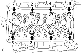
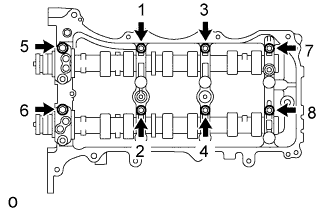
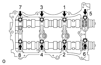
Using a 10 mm bi-hexagon wrench, install and uniformly tighten the 8 cylinder head bolts with the plate washers in several steps and in the sequence shown in the illustration.
36 N*m 367 kgf*cm 27 ft.*lbf
-
-
Step 2
-
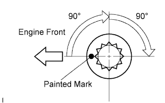
Mark the cylinder head bolt head with paint as shown in the illustration.
-
Tighten the cylinder head bolts another 90°.
-
-
Step 3
-
Tighten the cylinder head bolts an additional 90°.
-
Check that the painted mark is now facing rearward.
-
-
- Click here
INSTALL CYLINDER HEAD GASKET LH
-
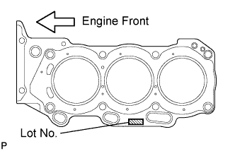
Place a new cylinder head gasket LH on the cylinder block surface with the Lot No. stamp upward.
Note:
-
Be careful of the installation direction.
-
Gently lower the cylinder head in order not to damage the gasket with the bottom part of the head.
-
-
- Click here
INSTALL CYLINDER HEAD SUB-ASSEMBLY LH
-
Place the cylinder head on the cylinder block.
Note:Be careful not to allow oil to adhere to the bottom part of the cylinder head.
Tip:The cylinder head bolts are tightened in 3 progressive steps.
-
Apply a light coat of engine oil to the threads and under the heads of the cylinder head bolts.
-
Step 1
-
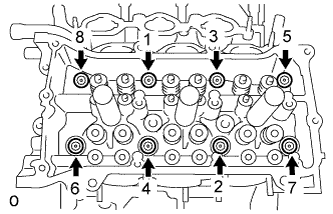
Using a 10 mm bi-hexagon wrench, install and uniformly tighten the 8 cylinder head bolts with the plate washers in several steps in the sequence shown in the illustration.
36 N*m 367 kgf*cm 27 ft.*lbf
-
-
Step 2
-
Mark the cylinder head bolt head with paint as shown in the illustration.
-
Tighten the cylinder head bolts another 90°.
-
-
Step 3
-
Tighten the cylinder head bolts an additional 90°.
-
Check that the painted mark is now facing rearward.
-
-
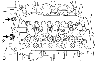
Tighten the 2 bolts in the order shown in the illustration.
30 N*m 306 kgf*cm 22 ft.*lbf
-
- Click here
INSTALL WATER OUTLET
-
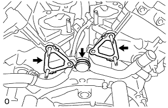
Install 2 new gaskets and a new O-ring.
Tip:Apply soapy water to the O-ring.
-
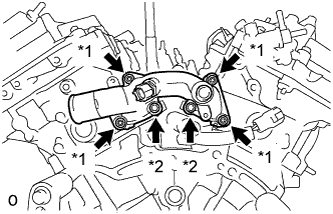
Install the water outlet with the 2 bolts and 4 nuts.
Table 1. Text in Illustration *1 Nut *2 Bolt 10 N*m 102 kgf*cm 7 ft.*lbf Note:Be careful that the O-ring does not get caught between the parts.
-
- Click here
INSTALL VALVE STEM CAP
-
Install the 24 valve stem caps.
-
- Click here
INSTALL VALVE LASH ADJUSTER ASSEMBLY
Note:
-
Keep the lash adjuster free of dirt and foreign objects.
-
Only use clean engine oil.
-
Place the lash adjuster into a container filled with engine oil.
-
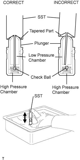
Insert the tip of SST into the lash adjuster plunger and use the tip to press down on the check ball inside the plunger.
09276-75010 -
Squeeze SST and lash adjuster together to move the plunger up and down 5 to 6 times.
-
Check the movement of the plunger and bleed the air.
OK Plunger moves up and down. Note:When bleeding air from the high-pressure chamber, make sure that the tip of SST is actually pressing the check ball as shown in the illustration. If the check ball is not pressed, air will not bleed.
-
After bleeding the air, remove SST. Then, try to press the plunger quickly and firmly by hand.
OK Plunger is very difficult to move. If the result is not as specified, replace the valve lash adjuster.
-
Install the valve lash adjusters.
Note:Install each valve lash adjuster to the same place it was removed from.
-
- Click here
INSTALL NO. 1 VALVE ROCKER ARM SUB-ASSEMBLY
-
Apply engine oil to the lash adjuster tip and valve stem cap end.
-
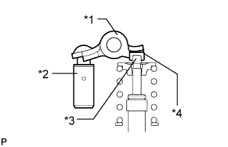
Install the valve rocker arms as shown in the illustration.
Table 2. Text in Illustration *1 Valve Rocker Arm *2 Lash Adjuster *3 Valve Stem *4 Valve Stem Cap
-
- Click here
INSTALL NO. 3 CAMSHAFT
-
Apply a light coat of engine oil to the No. 3 camshaft journals and camshaft housing sub-assembly LH.
-
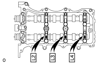
Install the No. 3 camshaft to the camshaft housing sub-assembly LH.
-
- Click here
INSTALL NO. 4 CAMSHAFT
-
Apply a light coat of engine oil to the No. 4 camshaft journals and camshaft housing sub-assembly LH.
-
Install the No. 4 camshaft to the camshaft housing sub-assembly LH.
-
- Click here
INSTALL CAMSHAFT BEARING CAP (for Bank 2)
-
Apply engine oil to the camshaft bearing caps.
-
Make sure of the marks and numbers on the camshaft bearing caps and place them in each proper position and direction.
-
Temporarily tighten the 8 bolts in the order shown in the illustration.
10 N*m 102 kgf*cm 7 ft.*lbf
-
- Click here
INSTALL CAMSHAFT HOUSING SUB-ASSEMBLY LH
-
Make sure that the valve rocker arm is installed as shown in the illustration.
Table 3. Text in Illustration *1 Valve Rocker Arm *2 Lash Adjuster *3 Valve Stem *4 Valve Stem Cap -
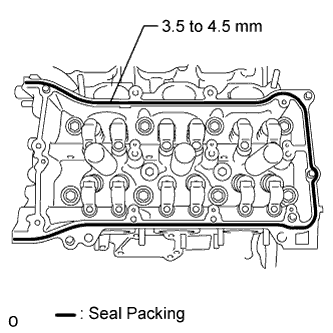
Apply seal packing in a continuous line as shown in the illustration.
Seal packing Toyota Genuine Seal Packing Black, Three Bond 1207B or equivalent Standard seal diameter 3.5 to 4.5 mm (0.138 to 0.177 in.) Note:
-
Remove any oil from the contact surface.
-
Install the camshaft housing sub-assembly LH within 3 minutes.
-
Do not start the engine for at least 2 hours after installing.
-
-
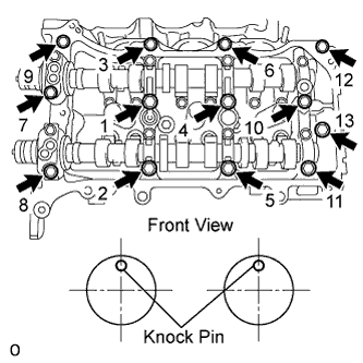
Install the camshaft housing sub-assembly LH and tighten the 13 bolts in the order shown in the illustration.
28 N*m 286 kgf*cm 21 ft.*lbf Note:
-
When installing the camshaft housing sub-assembly LH, it is necessary to correctly position the camshafts as shown in the illustration. Failure to correctly position these parts may result in damage due to contact between the pistons and valves. If a camshaft is rotated with a piston at TDC, valve contact will occur.
-
If any of the bolts are loosened during installation, remove the camshaft housing sub-assembly LH, clean the installation surfaces, and reapply seal packing.
-
If the camshaft housing sub-assembly LH is removed because any of the bolts are loosened during installation, make sure that the previously applied seal packing does not enter any oil passages.
-
-
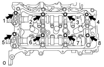
Tighten the 8 bolts in the order shown in the illustration.
16 N*m 163 kgf*cm 12 ft.*lbf
-
- Click here
INSTALL CAMSHAFT
-
Apply a light coat of engine oil to the camshaft journals and camshaft housing sub-assembly RH.
-
Install the camshaft to the camshaft housing sub-assembly RH.
-
- Click here
INSTALL NO. 2 CAMSHAFT
-
Apply a light coat of engine oil to the No. 2 camshaft journals and camshaft housing sub-assembly RH.
-
Install the No. 2 camshaft to the camshaft housing sub-assembly RH.
-
- Click here
INSTALL CAMSHAFT BEARING CAP (for Bank 1)
-
Apply engine oil to the camshaft bearing caps.
-
Make sure of the marks and numbers on the camshaft bearing caps and place them in each proper position and direction.
-
Temporarily tighten the 8 bearing cap bolts in the order shown in the illustration.
10 N*m 102 kgf*cm 7 ft.*lbf
-
- Click here
INSTALL CAMSHAFT HOUSING SUB-ASSEMBLY RH
Tip:See the steps from "Install Camshaft Housing Sub-Assembly RH" through "Install Automatic Transaxle Assembly" (Click here).