FUEL TANK INSTALLATION

-
INSTALL TANK SUCTION TUBE SUPPORT
-
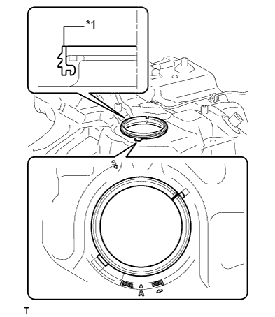
Text in Illustration *1 Tank Suction Tube Support Install a new tank suction tube support as shown in the illustration.
-
-
INSTALL FUEL TANK CUSHION SET
-

Text in Illustration *1 Fuel Tank Cushion Set *2 No. 5 Fuel Tank Cushion Install the fuel tank cushion sets and No. 5 fuel tank cushions.
-
-
INSTALL FUEL TANK TO FILLER PIPE HOSE
-

Install the fuel tank to filler pipe hose with the hose clamp.
-
-
INSTALL FUEL TANK MAIN TUBE SUB-ASSEMBLY
-

Text in Illustration *1 Claw Install the fuel pump tube, and engage the 2 claws.
-
-
INSTALL NO. 2 FUEL TANK SIDE PLATE
-

Install a new No. 2 fuel tank side plate.
-
-
INSTALL FUEL TANK ASSEMBLY
-
Set the fuel tank onto an engine lifter.
-
Operating the engine lifter, install the fuel tank.
Note
Slowly raise the lifter so as not to drop the fuel tank assembly.
-
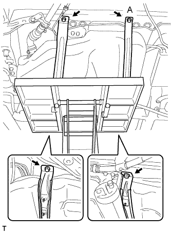
Install the 2 fuel tank bands with the 4 bolts.
- Torque:
- 45 N*m { 459 kgf*cm, 33 ft.*lbf }
Tech Tips
-
Using a 14 mm union nut wrench, tighten the A bolt.
-
Use the formula to calculate special torque values for situations where union nut wrench is combined with a torque wrench Click here.
-
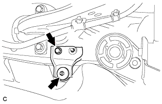
Install the rear fuel tank bracket LH with the bolt and nut.
- Torque:
- Bolt
- 45 N*m { 459 kgf*cm, 33 ft.*lbf }
- Nut
- 20 N*m { 200 kgf*cm, 14 ft.*lbf }
-
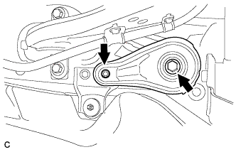
Install the rear lower suspension member stopper LH with the bolt and nut.
- Torque:
- Bolt
- 180 N*m { 1837 kgf*cm, 133 ft.*lbf }
- Nut
- 32 N*m { 327 kgf*cm, 24 ft.*lbf }
-

Tighten the bolt.
- Torque:
- 20 N*m { 200 kgf*cm, 14 ft.*lbf }
-
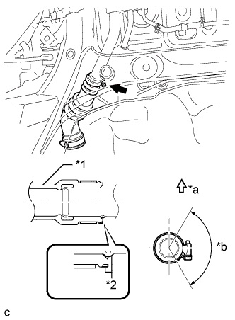
Text in Illustration *1 Fuel Tank to Filler Pipe Hose *2 Matchmark *a Upper Side *b 120° Align the matchmarks and install the fuel tank to filler pipe hose to the fuel tank.
-
Install the hose clamp within the range shown in the illustration.
-
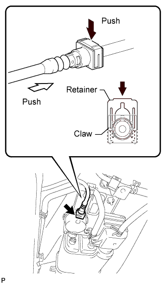
Text in Illustration *1 Retainer *2 Claw *a Push Connect the vent line tube.
-
Line up the 2 parts of the port to be connected, and fully push the vent line tube connector and port together until they are fully seated. Next, push the retainer into the connector until its claws lock.
-
After connecting the tube, check that the port and connector are securely connected by pulling on them.
-
-
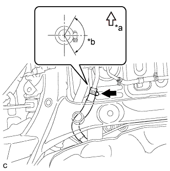
Text in Illustration *a Upper Side *b 120° Connect the fuel tank breather tube sub-assembly with the clamp.
-
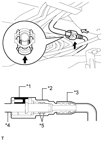
Text in Illustration *1 Retainer *2 Quick Connector *3 Nylon Tube *4 Pipe *5 O-ring Connect the fuel tank main tube sub-assembly.
-
Push the quick connector and push in the retainer to lock the claws.
Note
-
Check if there is any damage or foreign objects on the connected part.
-
After connecting, check if the quick connector and the pipe are securely connected by pulling on them.
-
-
-
-
INSTALL NO. 1 FUEL TANK PROTECTOR SUB-ASSEMBLY
-

Install the No. 1 fuel tank protector sub-assembly with the 7 nuts.
- Torque:
- 5.5 N*m { 56 kgf*cm, 49 in.*lbf }
-
Install 3 new clips (A).
-
-
INSTALL CHARCOAL CANISTER PROTECTOR
-
Install the charcoal canister protector with the 3 bolts.
- Torque:
- 5.5 N*m { 56 kgf*cm, 49 in.*lbf }
-
-
INSTALL FRONT CENTER FLOOR COVER
-
Install the front center floor cover with the 4 clips.
-
Install the nut and 2 screws.
-
-
INSTALL FRONT FLOOR COVER LH
-
INSTALL EXHAUST TAIL PIPE ASSEMBLY
-
INSTALL FUEL SUCTION TUBE ASSEMBLY WITH PUMP AND GAUGE
-
INSPECT EXHAUST GAS LEAK