FUEL PUMP INSTALLATION

-
INSTALL FUEL SUCTION TUBE ASSEMBLY WITH PUMP AND GAUGE
-
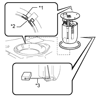
Text in Illustration *1 Keyway *2 Key *3 Arm Install a new gasket to the fuel tank.
-
Attach the fuel suction tube with pump and gauge to the fuel tank.
Note
Be careful not to bend the arm of the fuel sender gauge.
-
Align the keyway of the fuel suction tube support with the key of the fuel suction tube assembly with pump and gauge.
-
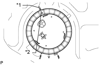
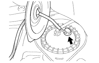
Text in Illustration *1 "S" Mark *2 Triangle Mark Align the triangle mark on a new fuel pump gauge retainer with the "S" mark on the fuel tank while pushing down the fuel suction tube with pump and gauge, and attach the fuel pump gauge retainer.
-
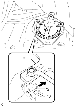
Text in Illustration *1 SST
(Plate)
*2 SST
(Claw)
*3 Rib Using a wrench, temporarily install the SST plate and claws to the fuel pump gauge retainer.
- SST
- 09808-14030 ( 09808-01010, 09808-01020, 09808-01030, 09808-01040, 09808-01050 )
-
While pressing the claws of SST to the fuel pump gauge retainer ribs securely, tighten the bolts.
Tech Tips
Install SST while pressing the SST claws toward the fuel pump gauge retainer (toward the center of SST).
-
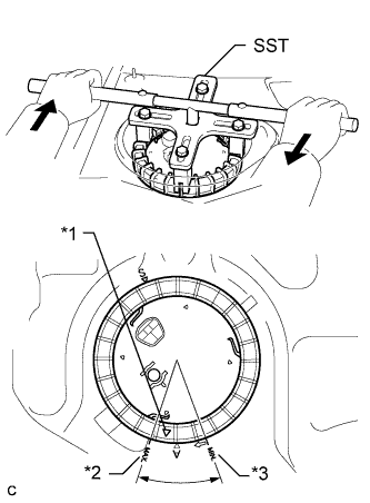
Text in Illustration *1 Triangle Mark *2 "MAX" Mark *3 "MIN" Mark Rotate the fuel pump gauge retainer by hand, then tighten it one complete turn and another half turn using SST. The triangle mark on the fuel pump gauge retainer must be positioned between the "MIN" and "MAX" marks on the fuel tank.
- SST
- 09808-14030 ( 09808-01010, 09808-01020, 09808-01030, 09808-01040, 09808-01050 )
Note
-
Do not use any tools other than specified in this operation. Damage to the fuel pump gauge retainer or the fuel tank may result.
-
Do not press down on SST excessively as this may make the retainer hard to rotate, and may damage components.
-
Make sure to rotate the SST handle horizontally. If the SST handle is rotated at an angle, SST may come off.
-
Do not spin SST too fast or use an impact wrench as this may result in damage to components.
-
If SST comes off of the retainer, loosen the SST bolts and reinstall SST.
Tech Tips
-
Lightly press down on SST to prevent it from separating from the retainer. While pressing SST, rotate the handle slowly to tighten the retainer.
-
The ribs on the fuel pump gauge retainer can be fitted into the tips of SST.
-
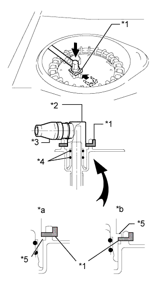
Text in Illustration *1 Tube Joint Clip *2 Fuel Tube Joint *3 Fuel Tube *4 O-ring *5 Collar *a CORRECT *b INCORRECT Install the fuel tank main tube sub-assembly and the tube joint clip.
Note
-
Check that there are no scratches or foreign matter on the connecting part.
-
Check that the fuel tube joint is inserted securely.
-
Check that the tube joint clip is correctly located on the collar of the fuel tube joint.
-
After installing the tube joint clip, check that the fuel tube joint has not been pulled out of position.
-
-
Connect the fuel pump connector.
-
-
CONNECT CABLE TO NEGATIVE BATTERY TERMINAL
Note
When disconnecting the cable, some systems need to be initialized after the cable is reconnected Click here.
-
INSPECT FOR FUEL LEAK
-
Check fuel pump operation.
-
Connect the intelligent tester to the DLC3.
-
Turn the engine switch on (IG) and turn the intelligent tester on.
Note
Do not start the engine.
-
Enter the following menus: Powertrain / Engine / Active Test / Control the Fuel Pump / Speed.
-
Check for pressure in the fuel inlet tube from the fuel line. Check that sounds of fuel flowing from the fuel tank can be heard. If no sounds can be heard, check the integration relay, fuel pump, ECM and wiring connectors.
-
-
Check for fuel leaks.
-
Check that there are no fuel leaks from the fuel system after doing any maintenance or repairs. If there is a fuel leak, repair or replace parts as necessary.
-
-
Turn the engine switch off.
-
Disconnect the intelligent tester from the DLC3.
-
-
INSTALL REAR FLOOR SERVICE HOLE COVER
-
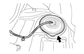
Install new butyl tape to the rear floor service hole cover.
-
Install the rear floor service hole cover.
-
Install the front floor carpet with the clip.
-
-
INSTALL REAR DOOR OPENING TRIM WEATHERSTRIP LH
-
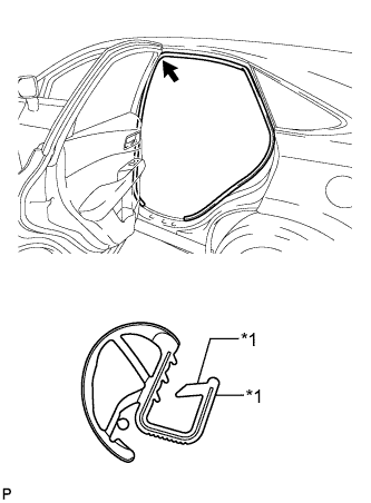
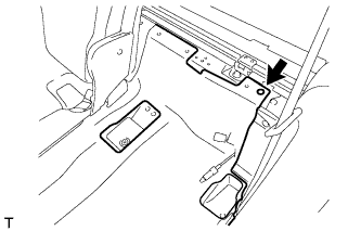
Text in Illustration *1 Alignment mark (Brown) Align the alignment mark (Brown) on the weatherstrip with the protruding portion on the body indicated by the arrow in the illustration, and install the rear door opening trim weatherstrip LH.
Note
After installation, check that the corners fit correctly.
-
-
INSTALL REAR DOOR SCUFF PLATE LH
-
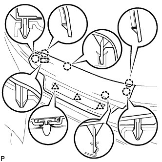
Engage the 3 clips, guide and 6 claws, and install the rear door scuff plate LH.
-
-
INSTALL REAR SEAT ASSEMBLY LH