ENGINE UNIT INSTALLATION

-
INSTALL IGNITION COIL ASSEMBLY
-
Install the 4 ignition coil assemblies with the 4 bolts.
- Torque:
- 10 N*m { 102 kgf*cm, 7 ft.*lbf }
-
Connect the 4 ignition coil assembly connectors.
-
-
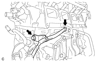
INSTALL ENGINE COOLANT TEMPERATURE SENSOR
-
Install a new gasket to the engine coolant temperature sensor.
-
Using a 19 mm ball joint lock nut wrench, install the engine coolant temperature sensor.
- Torque:
- 20 N*m { 204 kgf*cm, 15 ft.*lbf }
Note
Use the formula to calculate special torque values for situations where a ball joint lock nut wrench is combined with a torque wrench Click here.
-
Connect the engine coolant temperature sensor connector.
-
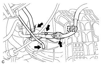
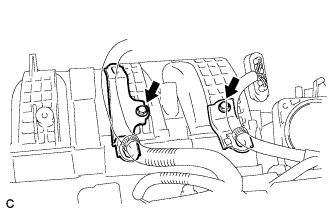
Install the wire harness with the 2 bolts.
- Torque:
- 8.4 N*m { 86 kgf*cm, 74 in.*lbf }
-
Connect the air fuel ratio sensor connector clamp.
-
-
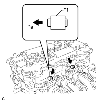
INSTALL ENGINE OIL PRESSURE SWITCH ASSEMBLY
-
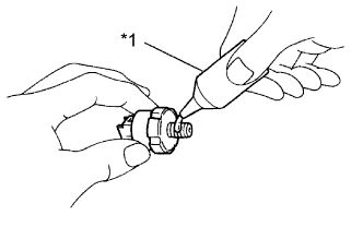
Text in Illustration *1 Adhesive Apply adhesive to 2 or 3 threads of the oil pressure switch.
Adhesive Toyota Genuine Adhesive 1344, Three Bond 1344 or equivalent. Note
Do not let adhesive adhere to the oil hole.
-
Using a 24 mm deep socket wrench, install the oil pressure switch.
- Torque:
- 15 N*m { 153 kgf*cm, 11 ft.*lbf }
Note
Do not start the engine within 1 hour of installation.
-
Connect the oil pressure switch connector.
-
-
INSTALL KNOCK CONTROL SENSOR
-
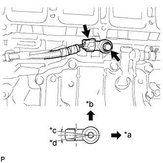
Text in Illustration *a Front of Engine *b Up *c 7° *d 10° Install the sensor with the bolt so that the sensor is angled as shown in the illustration.
- Torque:
- 20 N*m { 204 kgf*cm, 15 ft.*lbf }
Note
The acceptable installation angle of the sensor is between 7° upward and 10° downward from the horizontal position.
-
Connect the sensor connector.
-
-
INSTALL SENSOR WIRE
-
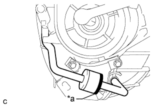
Install the sensor wire with the bolt.
- Torque:
- 21 N*m { 214 kgf*cm, 15 ft.*lbf }
-
Connect the knock control sensor connector.
-
-
INSTALL INTAKE MANIFOLD
-
Install the wire harness clamp bracket with the bolt.
- Torque:
- 10 N*m { 102 kgf*cm, 7 ft.*lbf }
-
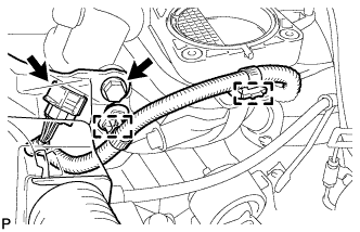
Text in Illustration *a Black Connect the 2 vacuum hoses and check that the check valve is installed as shown in the illustration.
-
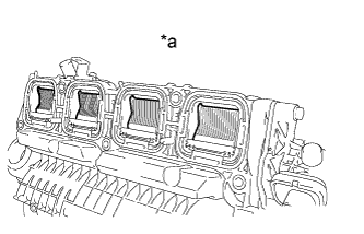
Text in Illustration *a Condition: Closed Check the tumble control valves.
Note
The tumble control valves may be damaged if they are not closed before installing the intake manifold.
Tech Tips
Connect the battery to the terminals of the actuator to operate the motor and close the valves Click here.
-
Install a new gasket to the intake manifold.
-
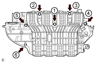
Install the intake manifold by tightening the 6 bolts in the sequence shown in the illustration.
- Torque:
- 21 N*m { 214 kgf*cm, 15 ft.*lbf }
-
Connect the intake air control actuator connector and 2 wire harness clamps.
-
Install the wire harness clamp with the bolt.
- Torque:
- 10 N*m { 102 kgf*cm, 7 ft.*lbf }
-
Install the wire harness clamp bracket with the bolt.
- Torque:
- 10 N*m { 102 kgf*cm, 7 ft.*lbf }
-
Connect the wire harness clamp and connector.
-
Connect the fuel vapor feed hose and vacuum hose.
-
Install the 2 wire harness clamp brackets with the 2 bolts.
- Torque:
- 10 N*m { 102 kgf*cm, 7 ft.*lbf }
-
-
CONNECT NO. 2 VENTILATION HOSE
-
Connect the No. 2 ventilation hose to the intake manifold.
-
-
INSTALL FUEL DELIVERY PIPE SUB-ASSEMBLY
-
Text in Illustration *1 Fuel Delivery Spacer *a Cylinder Head Side Install the 2 fuel delivery spacers onto the cylinder head.
Tech Tips
Install the fuel delivery spacer so that the longer protrusion is on the cylinder head side.
-
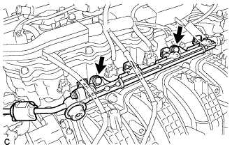
Install the fuel delivery pipe sub-assembly with the 4 fuel injector assemblies and install the 2 bolts.
- Torque:
- 21 N*m { 214 kgf*cm, 15 ft.*lbf }
Note
-
Do not drop the fuel injectors when installing the fuel delivery pipe sub-assembly.
-
Check that the fuel injector assemblies rotate smoothly after installing the fuel delivery pipe sub-assembly.
-
-
INSTALL WATER BY-PASS HOSE
-
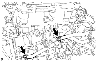
Install the No. 1 and No. 2 water by-pass hoses.
-
-
INSTALL THROTTLE BODY ASSEMBLY
-
Install the fuel tube bracket with the bolt.
- Torque:
- 7.5 N*m { 76 kgf*cm, 66 in.*lbf }
-
Install a new gasket to the intake manifold.
-
Install the throttle body assembly with the 4 bolts.
- Torque:
- 10 N*m { 102 kgf*cm, 7 ft.*lbf }
-
Connect the 2 water by-pass hoses to the throttle body.
-
Connect the throttle body assembly connector.
-
Connect the fuel tube to the clamp.
-
-
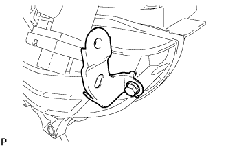
INSTALL NO. 1 COMPRESSOR MOUNTING BRACKET
-
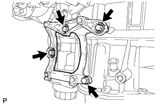
Install the bracket with the 4 bolts.
- Torque:
- 21 N*m { 214 kgf*cm, 15 ft.*lbf }
-
-
INSTALL EXHAUST MANIFOLD CONVERTER SUB-ASSEMBLY
-
Install a new exhaust manifold to head gasket onto the cylinder head.
-
Temporarily install the exhaust manifold converter sub-assembly with the 5 nuts.
-
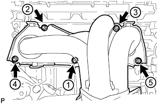
Tighten the 5 nuts in the sequence shown in the illustration.
- Torque:
- 35 N*m { 357 kgf*cm, 26 ft.*lbf }
-
-
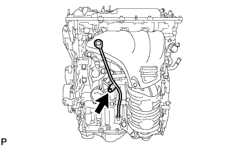
INSTALL NO. 2 MANIFOLD STAY
-
Install the No. 2 manifold stay with the bolt and nut.
- Torque:
- 43 N*m { 438 kgf*cm, 32 ft.*lbf }
-
-
INSTALL MANIFOLD STAY
-
Install the manifold stay with the bolt and nut.
- Torque:
- 43 N*m { 438 kgf*cm, 32 ft.*lbf }
-
-
INSTALL NO.1 EXHAUST MANIFOLD HEAT INSULATOR
-
Install the No. 1 exhaust manifold heat insulator with the 4 bolts.
- Torque:
- 12 N*m { 122 kgf*cm, 9 ft.*lbf }
-
-
INSTALL ENGINE OIL LEVEL DIPSTICK GUIDE
-
Apply a light coat of engine oil to a new O-ring.
-
Install the O-ring to the engine oil level dipstick guide.
-
Install the engine oil level dipstick guide with the bolt.
- Torque:
- 10 N*m { 102 kgf*cm, 7 ft.*lbf }
-
Install the engine oil level dipstick.
-