CYLINDER HEAD GASKET INSTALLATION

-
INSPECT CYLINDER HEAD BOLT
-
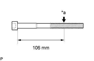
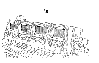
Text in Illustration *a Measurement Point Using a vernier caliper, measure the diameter of the threads at the measurement point shown in the illustration.
Standard diameter 10.85 to 11.00 mm (0.427 to 0.433 in.) Minimum diameter 10.6 mm (0.417 in.) Measurement point (distance from the seat) 106 mm (4.17 in.) Tech Tips
-
If the diameter is less than the minimum, replace the cylinder head bolt with a new one. Failure to do so may lead to engine damage.
-
If there is any thread deformation, replace the cylinder head bolt with a new one.
-
-
-
INSPECT CYLINDER HEAD SUB-ASSEMBLY
-
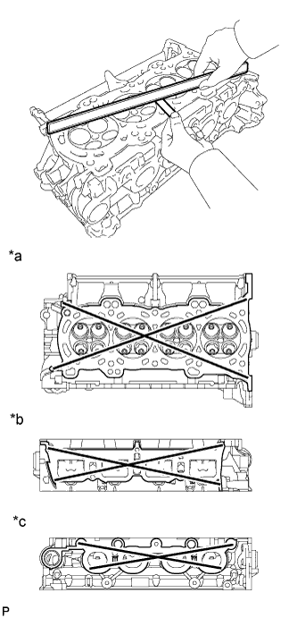
Text in Illustration *a Cylinder Head Lower Side *b Intake Manifold Side *c Exhaust Manifold Side Using a precision straightedge and feeler gauge, measure the warpage of the contact surfaces where the cylinder head contacts the cylinder block and manifold.
Maximum Warpage Item Specified Condition Cylinder head lower side 0.05 mm (0.00197 in.) Intake manifold side 0.10 mm (0.00394 in.) Exhaust manifold side 0.10 mm (0.00394 in.) If the warpage is more than the maximum, replace the cylinder head.
-
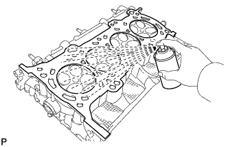
Using a dye penetrant, check the intake ports, exhaust ports and cylinder surface for cracks.
If cracked, replace the cylinder head.
-
-
INSTALL CYLINDER HEAD GASKET
-
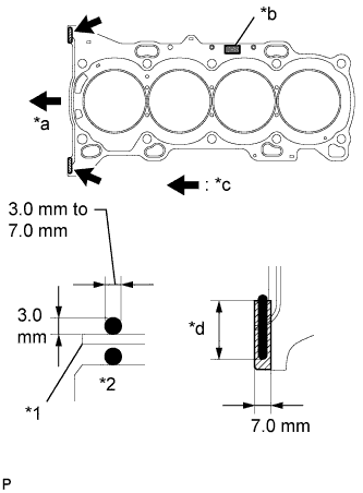
Text in Illustration *1 Cylinder Head Gasket *2 Cylinder Block *a Front *b Lot No. *c Seal Packing *d 20mm or more Clean the cylinder block and cylinder head with solvent.
-
Apply a continuous line of seal packing to a new cylinder head gasket as shown in the illustration.
Seal packing Toyota Genuine Seal Packing Black, Three Bond 1207B or equivalent Standard seal dimension 3.0 to 7.0 mm (0.118 to 0.276 in.) wide and 3.0 mm (0.118 in.) thick Tech Tips
Apply at least 20 mm (0.787 in.) of seal packing from the inside edge of the protrusion of the cylinder block.
Note
-
Remove any oil from the contact surface.
-
Install the cylinder head gasket within 3 minutes and tighten the bolts within 15 minutes after applying seal packing.
-
-
Place a new cylinder head gasket on the cylinder block surface with the front face of the Lot No. stamp upward.
Note
Pay attention to the installation direction.
-
-
INSTALL CYLINDER HEAD SUB-ASSEMBLY
Tech Tips
The cylinder head bolts are tightened in 4 progressive steps.
-
Place the cylinder head on the cylinder block.
Note
-
Ensure that no oil is on the mounting surface of the cylinder head.
-
Place the cylinder head on the cylinder block gently in order not to damage the gasket with the bottom part of the head.
-
-
Install the plate washers to the cylinder head bolts.
-
Apply a light coat of engine oil to the threads and under the heads of the cylinder head bolts.
-
Step 1:
-
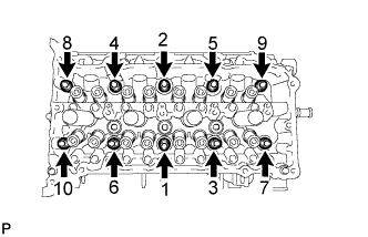
Using a 10 mm bi-hexagon wrench, install and uniformly tighten the 10 cylinder head bolts in several steps, in the sequence shown in the illustration.
- Torque:
- 36 N*m { 367 kgf*cm, 27 ft.*lbf }
Note
Do not drop the plate washer for the cylinder head bolt into the cylinder head.
-
-
Step 2:
-
Tighten the cylinder head bolts again in the sequence shown in the illustration to make sure that they are tightened to the specified torque.
- Torque:
- 36 N*m { 367 kgf*cm, 27 ft.*lbf }
-
-
Step 3:
-
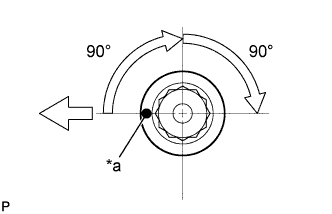
Text in Illustration *a Paint Mark 
Front Mark each cylinder head bolt head with paint as shown in the illustration.
-
Tighten the cylinder head bolts 90° in the sequence shown in step 1.
-
-
Step 4:
-
Tighten the cylinder head bolts another 90° in the sequence shown in step 1.
-
Check that the painted marks are now facing rearward.
Note
-
Do not add engine oil for at least 4 hours after the installation.
-
Do not start the engine for at least 4 hours after the installation.
-
After the installation, if the seal packing has seeped out, wipe it off.
-
-
-
-
INSTALL VALVE STEM CAP
-
Apply a light coat of engine oil to the valve stem ends.
-
Install the 16 valve stem caps to the cylinder head.
Note
Do not drop the valve stem caps into the cylinder head.
-
-
INSTALL CAMSHAFT
-
INSTALL INTAKE MANIFOLD
-
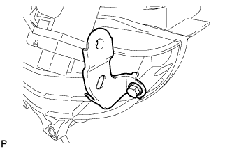
Install the wire harness clamp bracket with the bolt.
- Torque:
- 10 N*m { 102 kgf*cm, 7 ft.*lbf }
-
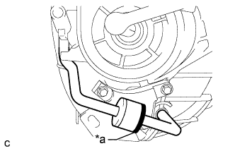
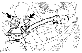
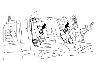
Text in Illustration *a Black Connect the 2 vacuum hoses and check that the check valve is installed as shown in the illustration.
-
Text in Illustration *a Condition: Closed Check the tumble control valves.
Note
The tumble control valves may be damaged if they are not closed before installing the intake manifold.
Tech Tips
Connect the battery to the terminals of the actuator to operate the motor and close the valves Click here.
-
Install a new gasket to the intake manifold.
-
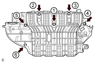
Install the intake manifold by tightening the 6 bolts in the sequence shown in the illustration.
- Torque:
- 21 N*m { 214 kgf*cm, 15 ft.*lbf }
-
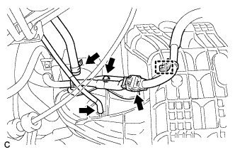
Connect the intake air control actuator connector and 2 wire harness clamps.
-
Install the wire harness clamp with the bolt.
- Torque:
- 10 N*m { 102 kgf*cm, 7 ft.*lbf }
-
Install the wire harness clamp bracket with the bolt.
- Torque:
- 10 N*m { 102 kgf*cm, 7 ft.*lbf }
-
Connect the wire harness clamp and connector.
-
Connect the fuel vapor feed hose and vacuum hose.
-
Install the 2 wire harness clamp brackets with the 2 bolts.
- Torque:
- 10 N*m { 102 kgf*cm, 7 ft.*lbf }
-
-
CONNECT NO. 2 VENTILATION HOSE
-
Connect the No. 2 ventilation hose to the intake manifold.
-
-
INSTALL FUEL DELIVERY PIPE SUB-ASSEMBLY
-
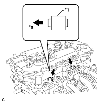
Text in Illustration *1 Fuel Delivery Spacer *a Cylinder Head Side Install the 2 fuel delivery spacers onto the cylinder head.
Tech Tips
Install the fuel delivery spacer so that the longer protrusion is on the cylinder head side.
-
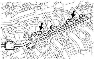
Install the fuel delivery pipe sub-assembly with the 4 fuel injector assemblies and install the 2 bolts.
- Torque:
- 21 N*m { 214 kgf*cm, 15 ft.*lbf }
Note
-
Do not drop the fuel injectors when installing the fuel delivery pipe sub-assembly.
-
Check that the fuel injector assemblies rotate smoothly after installing the fuel delivery pipe sub-assembly.
-
-
INSTALL THROTTLE BODY ASSEMBLY
-
Install the fuel tube bracket with the bolt.
- Torque:
- 7.5 N*m { 76 kgf*cm, 66 in.*lbf }
-
Install a new gasket to the intake manifold.
-
Install the throttle body assembly with the 4 bolts.
- Torque:
- 10 N*m { 102 kgf*cm, 7 ft.*lbf }
-
Connect the 2 water by-pass hoses to the throttle body.
-
Connect the throttle body assembly connector.
-
Connect the fuel tube to the clamp.
-
-
INSTALL EXHAUST MANIFOLD CONVERTER SUB-ASSEMBLY
-
INSTALL ENGINE ASSEMBLY WITH TRANSAXLE