AIR FUEL RATIO SENSOR INSTALLATION

-
INSTALL AIR FUEL RATIO SENSOR (for Bank 1 Sensor 1)
-
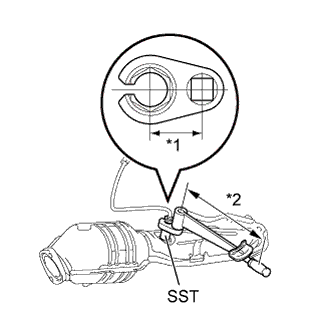
Text in Illustration *1 Fulcrum Length
30 mm
*2 Fulcrum Length
300 mm
Using SST, install the air fuel ratio sensor to the exhaust manifold RH.
- SST
- 09224-00010
- Torque:
- without SST
- 44 N*m { 449 kgf*cm, 33 ft.*lbf }
- with SST
- 40 N*m { 408 kgf*cm, 30 ft.*lbf }
Note
-
The "with SST" torque value is effective when using SST with a fulcrum length of 30 mm (1.18 in.).
-
The "with SST" torque value is effective when using a torque wrench with a fulcrum length of 300 mm (11.81 in.) Click here.
-
The "with SST" torque value is effective when SST is parallel to the torque wrench.
-
Connect the air fuel ratio sensor connector.
-
-
INSTALL AIR FUEL RATIO SENSOR NO.2 (for Bank 2 Sensor 1)
-
Use the same procedure for bank 1 and bank 2.
- SST
- 09224-00010
- Torque:
- without SST
- 44 N*m { 449 kgf*cm, 33 ft.*lbf }
- with SST
- 40 N*m { 408 kgf*cm, 30 ft.*lbf }
Note
-
The "with SST" torque value is effective when using SST with a fulcrum length of 30 mm (1.18 in.).
-
The "with SST" torque value is effective when using a torque wrench with a fulcrum length of 300 mm (11.81 in.) Click here.
-
The "with SST" torque value is effective when SST is parallel to the torque wrench.
-
-
INSTALL EXHAUST MANIFOLD
-
Install the exhaust manifold Click here.
-