CYLINDER HEAD GASKET REMOVAL

-
REMOVE ENGINE ASSEMBLY WITH TRANSAXLE
-
REMOVE EXHAUST MANIFOLD CONVERTER SUB-ASSEMBLY
-
REMOVE THROTTLE BODY ASSEMBLY
-
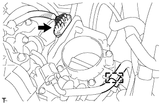
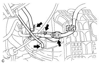
Disconnect the throttle body assembly connector.
-
Disconnect the fuel tube from the clamp.
-
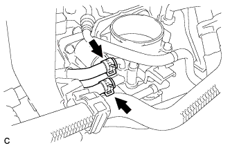
Disconnect the 2 water by-pass hoses from the throttle body assembly.
-
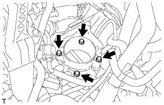
Remove the 4 bolts and the throttle body assembly.
-

Remove the bolt and fuel tube bracket.
-
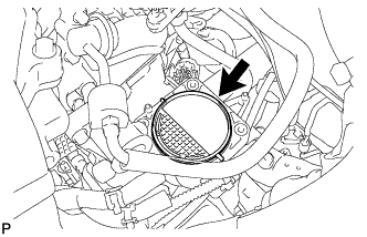
Remove the gasket from the intake manifold.
-
-
REMOVE FUEL DELIVERY PIPE SUB-ASSEMBLY
-
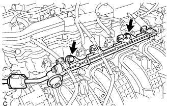
Remove the 2 bolts, and then remove the fuel delivery pipe together with the 4 fuel injectors.
Note
Be careful not to drop the fuel injectors when removing the fuel delivery pipe.
-
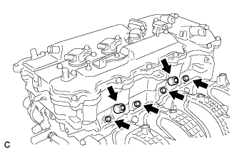
Remove the 2 fuel delivery spacers from the cylinder head.
-
Remove the 4 injector vibration insulators from the cylinder head.
-
-
DISCONNECT NO. 2 VENTILATION HOSE
-
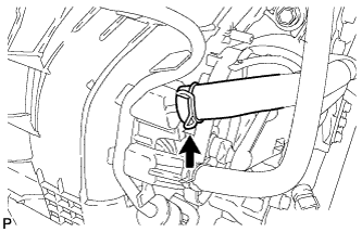
Disconnect the No. 2 ventilation hose from the intake manifold.
-
-
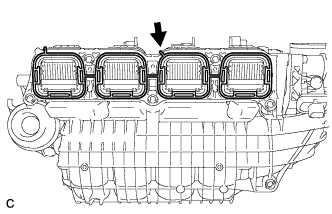
REMOVE INTAKE MANIFOLD
-
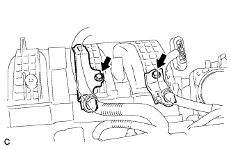
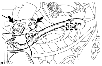
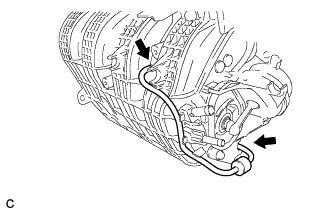
Remove the 2 bolts and 2 wire harness clamp brackets.
-
Disconnect the fuel vapor feed hose and vacuum hose.
-
Disconnect the wire harness clamp and connector.
-
Remove the bolt and wire harness clamp bracket.
-
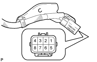
Apply battery voltage to the terminals of the connector to close the tumble control valves.
Standard Tester Connection Specified Condition Positive (+) battery voltage applied to terminal 8 (M-), and negative (-) battery voltage applied to terminal 4 (M+) Open → Closed Note
-
If this procedure is not performed, the tumble control valves may be damaged when the intake manifold is removed.
-
Apply battery voltage for 1 to 3 seconds.
-
If battery voltage is applied for more than 3 seconds, the actuator may be damaged.
-
Do not allow the lead wires to contact the other terminals.
-
-
-
Remove the bolt and separate the wire harness.
-
Disconnect the 2 wire harness clamps and intake air control valve actuator connector.
-
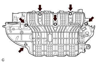
Remove the 6 bolts and intake manifold.
Note
The tumble control valves may be damaged if they are not closed before removing the intake manifold.
Tech Tips
Connect the battery to the terminals of the actuator to operate the motor and close the valves Click here.
-
Remove the intake manifold gasket from the intake manifold.
-
Disconnect the 2 vacuum hoses from the intake manifold and remove the check valve.
-
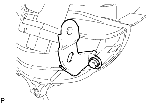
Remove the bolt and wire harness clamp bracket.
-
-
REMOVE CAMSHAFT
-
REMOVE VALVE STEM CAP
-
Remove the 16 valve stem caps from the cylinder head.
Tech Tips
Arrange the removed parts in the correct order.
-
-
REMOVE CYLINDER HEAD SUB-ASSEMBLY
-
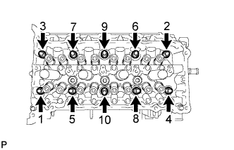
Using a 10 mm bi-hexagon wrench, uniformly loosen the 10 bolts in the sequence shown in the illustration. Remove the 10 cylinder head bolts and plate washers.
Tech Tips
Be sure to keep the removed parts separate for each installation position.
Note
-
Be careful not to drop washers into the cylinder head.
-
Head warpage or cracking could result from removing bolts in the incorrect order.
-
-
Remove the cylinder head.
-
-
REMOVE CYLINDER HEAD GASKET
-
Remove the cylinder head gasket from the cylinder block.
-