VACUUM SWITCHING VALVE (for Engine Mounting) REMOVAL

-
PRECAUTION (w/ Air Suspension)
Note
Be sure to read Precaution thoroughly before servicing Click here.
-
PRECAUTION (w/ Navigation System for HDD)
Note
After the engine switch is turned off, the display and navigation module display (HDD navigation system) records various types of memory and settings. As a result, after turning the engine switch off, make sure to wait for the time specified in the following table before disconnecting the cable from the negative (-) battery terminal.
Waiting Time before Disconnecting Cable from Negative (-) Battery Terminal Specification Waiting Time w/o Telematics transceiver 60 sec. w/ Telematics transceiver 120 sec. -
REMOVE ENGINE ROOM SIDE COVER (for LHD)
-
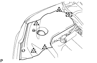
Remove the 4 clips.
-
Disengage the guide and remove the engine room side cover.
-
-
REMOVE ENGINE ROOM SIDE COVER (for RHD)
-
Remove the 4 clips.
-
Disengage the guide and remove the engine room side cover.
-
-
REMOVE ENGINE ROOM SIDE COVER LH (for LHD)
-
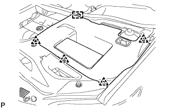
Remove the 4 clips.
-
Disengage the guide and remove the engine room side cover LH.
-
-
REMOVE ENGINE ROOM SIDE COVER LH (for RHD)
-
Remove the 4 clips.
-
Disengage the guide and remove the engine room side cover LH.
-
-
REMOVE COOL AIR INTAKE DUCT SEAL (for LHD)
-
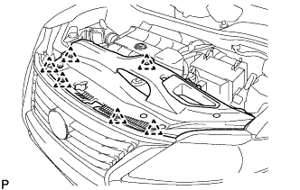
Remove the 6 clips and cool air intake duct seal.
-
-
REMOVE COOL AIR INTAKE DUCT SEAL (for RHD)
-
Remove the 6 clips and cool air intake duct seal.
-
-
DISCONNECT CABLE FROM NEGATIVE BATTERY TERMINAL
CAUTION:
Wait at least 90 seconds after disconnecting the cable from the negative (-) battery terminal to disable the SRS system.
Note
When disconnecting the cable, some systems need to be initialized after the cable is reconnected Click here.
-
REMOVE V-BANK COVER SUB-ASSEMBLY
-
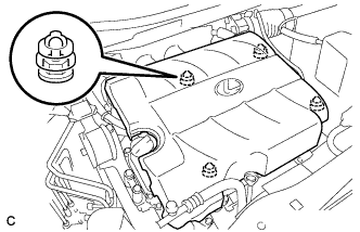
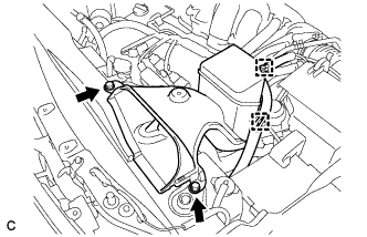
Hold the front of the V-bank cover sub-assembly and raise it to disengage the 2 retainers on the front of the V-bank cover sub-assembly. Continue to raise the V-bank cover sub-assembly to disengage the 2 retainers on the rear of the V-bank cover sub-assembly and remove the V-bank cover sub-assembly.
Note
Attempting to disengage both front and rear retainers at the same time may cause the V-bank cover sub-assembly to break.
-
-
REMOVE BATTERY
-
Disconnect the positive (+) cable from the positive (+) battery terminal.
-
Loosen the nut, and remove the bolt from the battery clamp.
-
Remove the battery and battery tray.
-
-
REMOVE NO. 2 AIR CLEANER INLET
-
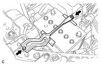
Disconnect the 2 vacuum hose clamps from the No. 2 air cleaner inlet.
-
Remove the 2 bolts and No. 2 air cleaner inlet.
-
-
REMOVE NO. 1 AIR CLEANER INLET
-
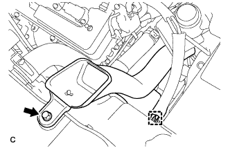
Disconnect the vacuum hose clamp from the No. 1 air cleaner inlet.
-
Remove the bolt and No. 1 air cleaner inlet.
-
-
REMOVE NO. 1 ENGINE UNDER COVER
-
REMOVE DUTY VACUUM SWITCHING VALVE
-
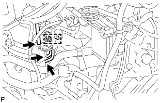
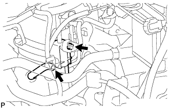
Disconnect the 3 vacuum hoses and separate the 2 vacuum hoses from the hose clamp.
-
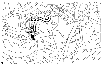
Disconnect the duty vacuum switching valve connector and the clamp.
-
Remove the bolt.
-
Disconnect the hose from the duty vacuum switching valve and remove the duty vacuum switching valve.
-