THROTTLE BODY INSTALLATION

-
INSTALL THROTTLE BODY
-
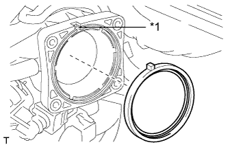
Text in Illustration *1 Recess Install a new gasket to the intake air surge tank assembly.
-
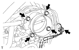
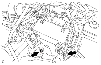
Install the throttle body and wire harness clamp stay to the intake air surge tank assembly with the 4 bolts.
- Torque:
- 10 N*m { 102 kgf*cm, 7 ft.*lbf }
-
Connect the throttle body connector and wire harness clamp.
-
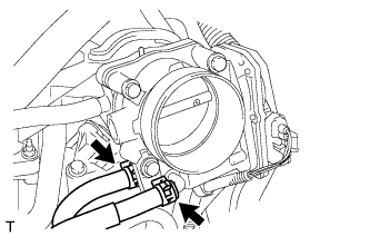
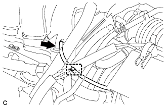
Connect the 2 water by-pass hoses to the throttle body.
-
-
INSTALL AIR CLEANER ASSEMBLY
-
Text in Illustration *1 Tab *2 Hole Insert the tab of the air cleaner assembly to the hole of the vehicle body as shown in the illustration.
-
Install the air cleaner assembly with the 2 bolts.
- Torque:
- 5.5 N*m { 56 kgf*cm, 49 in.*lbf }
-
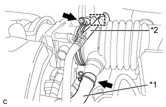
Text in Illustration *1 Ventilation Hose *2 Fuel Vapor Feed Hose Connect the air cleaner hose to the throttle body with the hose clamp.
-
Connect the ventilation hose and the fuel vapor feed hose.
-
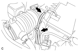
Connect the 2 vacuum hoses.
-
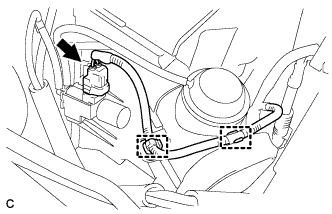
Connect the 2 wire harness clamps and vacuum switching valve connector.
-
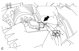
Connect the vacuum hose to the intake air surge tank assembly.
-
Install the hose to the hose clamp.
-
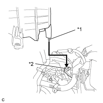
Connect the mass air flow meter connector and wire harness clamp.
-
-
INSTALL BATTERY
-
Install the battery and battery tray.
-
Install the battery clamp with the bolt and nut.
- Torque:
- 5.4 N*m { 55 kgf*cm, 48 in.*lbf }
-
Connect the positive (+) cable to the positive (+) battery terminal.
- Torque:
- 6.4 N*m { 65 kgf*cm, 57 in.*lbf }
-
-
INSTALL NO. 1 AIR CLEANER INLET
-
Install the No. 1 air cleaner inlet with the bolt.
- Torque:
- 8.0 N*m { 82 kgf*cm, 71 in.*lbf }
-
Connect the vacuum hose clamp to the No. 1 air cleaner inlet.
-
-
INSTALL NO. 2 AIR CLEANER INLET
-
Install the No. 2 air cleaner inlet with the 2 bolts.
- Torque:
- 8.0 N*m { 82 kgf*cm, 71 in.*lbf }
-
Connect the 2 vacuum hose clamps to the No. 2 air cleaner inlet.
-
-
CONNECT CABLE TO NEGATIVE BATTERY TERMINAL
Note
When disconnecting the cable, some systems need to be initialized after the cable is reconnected Click here.
-
ADD ENGINE COOLANT
-
Tighten the radiator drain cock plug by hand.
-
Tighten the cylinder block drain cock plug. (for Bank 1)
- Torque:
- 13 N*m { 130 kgf*cm, 9 ft.*lbf }
-
Tighten the cylinder block drain cock plug. (for Bank 2, w/ Cylinder Block Drain Cock Plug)
- Torque:
- 13 N*m { 130 kgf*cm, 9 ft.*lbf }
-
Loosen the air drain cock plug on the water inlet housing.
-
Add engine coolant to the radiator inlet opening until engine coolant overflows from the air drain cock hole. Then tighten the air drain cock plug to the water inlet housing.
- Torque:
- 13 N*m { 130 kgf*cm, 9 ft.*lbf }
-
Slowly fill the radiator assembly with engine coolant.
Standard capacity 9.5 liters (10.0 US qts, 8.3 Imp. qts) Note
Do not substitute plain water for engine coolant.
Tech Tips
TOYOTA vehicles are filled with TOYOTA SLLC at the factory. In order to avoid damage to the engine cooling system and other technical problems, only use TOYOTA SLLC or similar high quality ethylene glycol based non-silicate, non-amine, non-nitrite, non-borate coolant with long-life hybrid organic acid technology (coolant with long-life hybrid organic acid technology is a combination of low phosphates and organic acids).
-
Remove the reserve tank cap.
-
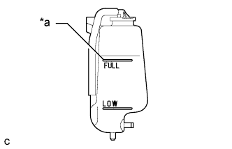
Text in Illustration *a Full Line Slowly pour engine coolant into the radiator reserve tank assembly until it reaches the full line.
-
Squeeze the No. 1 radiator hose and No. 2 radiator hose several times by hand, and then check the level of the engine coolant.
If the engine coolant level is low, add engine coolant.
-
Install the radiator cap sub-assembly and reserve tank cap.
-
Bleed air from the cooling system.
Note
-
Before starting the engine, turn the A/C switch off.
-
Adjust the heater control to the maximum hot setting.
-
Adjust the blower speed to the low setting.
-
Warm up the engine until the thermostat opens. While the thermostat is open, circulate the engine coolant for several minutes.
Tech Tips
The thermostat open timing can be confirmed by squeezing the No. 2 radiator hose by hand, and sensing vibrations when the engine coolant starts to flow inside the No. 2 radiator hose.
-
Maintain the engine speed at 2500 to 3000 rpm.
-
Squeeze the No. 1 radiator hose and No. 2 radiator hose several times by hand to bleed air.
CAUTION:
When squeezing the No. 1 radiator hose and No. 2 radiator hose:
-
Wear protective gloves.
-
Be careful as the No. 1 radiator hose and No. 2 radiator hose are hot.
-
Keep your hands away from the fan and No. 2 fan.
Note
-
If the coolant temperature gauge indicates an excessive temperature, turn off the engine and let it cool.
-
Make sure that the radiator reserve tank assembly still has some engine coolant in it.
-
If the radiator reserve tank assembly does not have enough engine coolant, the engine may overheat or be seriously damaged.
-
If the radiator reserve tank assembly does not have enough engine coolant, perform the following: 1) stop the engine, 2) wait until the engine coolant has cooled down, and 3) add engine coolant until the radiator reserve tank assembly is filled to the full line.
-
-
-
Stop the engine, and wait until the engine coolant cools down.
-
Add engine coolant to the full line on the radiator reserve tank assembly.
-
-
INSPECT FOR ENGINE COOLANT LEAK
CAUTION:
Do not remove the radiator cap while the engine and radiator are still hot. Pressurized, hot engine coolant and steam may be released and cause serious burns.
Note
Before performing each inspection, turn the A/C switch off.
-
Remove the radiator cap.
-
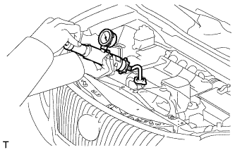
Fill the radiator with coolant and attach a radiator cap tester.
-
Warm up the engine.
-
Using the radiator cap tester, increase the pressure inside the radiator to 118 kPa (1.2 kgf/cm2, 17 psi), and check that the pressure does not drop.
If the pressure drops, check the hoses, radiator and water pump for leaks. If no external leaks are found, check the heater core, cylinder block and cylinder head.
-
Remove the radiator cap tester.
-
Install the radiator cap.
-
-
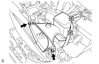
INSTALL OUTER COWL TOP PANEL SUB-ASSEMBLY (for LHD)
-
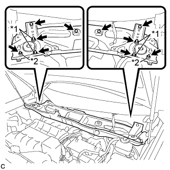
Install the outer cowl top panel sub-assembly with the 4 bolts, 4 nuts*1 and 2 nuts*2.
- Torque:
- Nut*1
- 85 N*m { 867 kgf*cm, 63 ft.*lbf }
- Nut*2
- 5.5 N*m { 56 kgf*cm, 49 in.*lbf }
- Bolt
- 5.5 N*m { 56 kgf*cm, 49 in.*lbf }
-
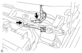
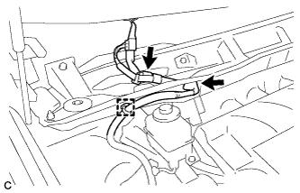
Engage the grommet and clamp to install the wire harness.
-
Connect the connector (w/ Windshield Deicer).
-
-
INSTALL OUTER COWL TOP PANEL SUB-ASSEMBLY (for RHD)
-
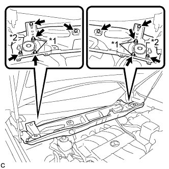
Install the outer cowl top panel sub-assembly with the 4 bolts, 4 nuts*1 and 2 nuts*2.
- Torque:
- Nut*1
- 85 N*m { 867 kgf*cm, 63 ft.*lbf }
- Nut*2
- 5.5 N*m { 56 kgf*cm, 49 in.*lbf }
- Bolt
- 5.5 N*m { 56 kgf*cm, 49 in.*lbf }
-
Engage the grommet and clamp to install the wire harness.
-
Connect the connector (w/ Windshield Deicer).
-
-
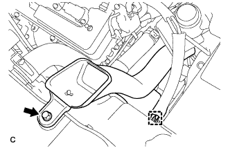
INSTALL FRONT SHOCK ABSORBER CAP (w/ Air Suspension)
-
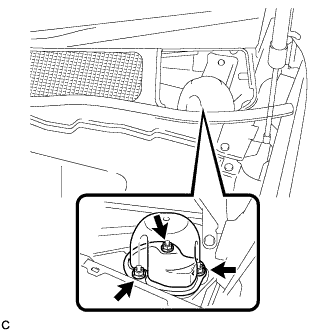
Install the front shock absorber cap with the 3 nuts.
- Torque:
- 14 N*m { 143 kgf*cm, 10 ft.*lbf }
-
-
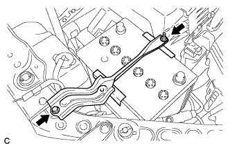
INSTALL WINDSHIELD WIPER MOTOR AND LINK ASSEMBLY
-
Install the windshield wiper motor and link assembly Click here.
-
-
INSTALL V-BANK COVER SUB-ASSEMBLY
-
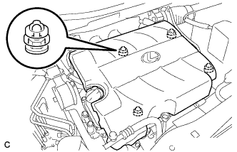
Fit the 4 retainers and install the V-bank cover sub-assembly.
-
-
INSTALL NO. 1 ENGINE UNDER COVER
-
PERFORM INITIALIZATION
Note
Perform the following procedure after replacing the ECM, throttle body assembly or any throttle body components. The following procedure should also be performed if the throttle body is cleaned.
-
Disconnect the cable from the negative (-) battery terminal. Wait at least 60 seconds and reconnect the cable.
-
Turn the engine switch on (IG) without operating the accelerator pedal.
Note
If the accelerator pedal is operated, perform the above steps again.
-
Connect the intelligent tester to the DLC3 and clear the DTCs Click here.
-
Start the engine and check that the MIL is not illuminated and that the idle speed is within the specified range when the A/C is switched off after the engine is warmed up.
Standard Condition Engine Idle Speed A/C switched off 600 to 700 rpm Note
-
Be sure to perform this step with all accessories off.
-
Make sure that the shift lever is in N.
-
-
Enter the following menus: Powertrain/ Engine / Data List/ Throttle Sensor Position. Fully depress the accelerator pedal and check that the value is 60% or more.
-
Perform a road test and confirm that there are no abnormalities.
-