CAMSHAFT INSTALLATION

-
SET CAMSHAFT TIMING GEAR ASSEMBLY
Tech Tips
When installing the camshaft timing gear assembly, release the lock pin and set the camshaft timing gear assembly to the advanced position before installation.
-
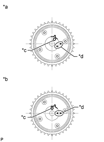
Text in Illustration *a Advanced Position *b Retarded Position *c Knock Pin Hole *d Alignment Mark Check the camshaft timing gear assembly position.
Note
If the camshaft timing gear assembly is set to the advanced position, do not let the camshaft timing gear assembly rotate clockwise during installation.
If the camshaft timing gear assembly rotates to the retarded position, release the lock pin and set the camshaft timing gear assembly to the advanced position.
-
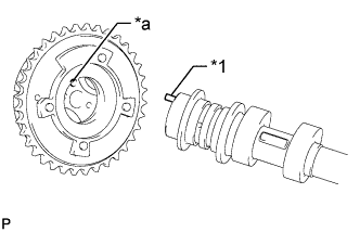
Text in Illustration *1 Knock Pin *a Knock Pin Hole Align and fit the knock pin of the No. 1 camshaft with the knock pin hole of the camshaft timing gear assembly.
-
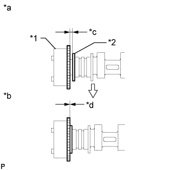
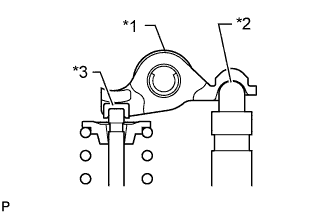
Text in Illustration *1 Camshaft Timing Gear Assembly *2 Camshaft Flange *a Incorrect *b Correct *c Clearance *d No Clearance Check that there is no clearance between the camshaft timing gear assembly and camshaft flange.
-
Secure the No. 1 camshaft in place by hand, and then install the installation bolt of the camshaft timing gear assembly by hand.
Note
Do not use any tools to install the bolt. If the bolt is installed using a tool, the lock pin will be damaged.
-
Release the lock pin.
Text in Illustration *1 Rubber *2 Vinyl Tape *3 Knock Pin *a Retard Side Path *b Advance Side Path *c Open *d Close
-
Clean the camshaft journal with non-residue solvent.
-
Cover the 4 oil paths of the camshaft journal with vinyl tape as shown in the illustration.
Tech Tips
There are 4 oil paths in the grooves of the No. 1 camshaft. Plug three of the paths with pieces of rubber.
-
Open a hole at port (A) shown in the illustration.
-
While applying approximately 200 kPa (2.0 kgf/ cm2, 29 psi) of air pressure to the oil path, forcibly turn the camshaft timing gear assembly in the advance direction (counterclockwise).
CAUTION:
Cover the paths with a piece of cloth when applying pressure to keep oil from spraying.
Note
Do not allow the camshaft timing gear assembly to lock. If it locks, release the lock pin again.
Tech Tips
-
Depending on the air pressure applied, the camshaft timing gear assembly may be turned in the advance direction without applying any force.
-
If enough air pressure cannot be applied because of air leakage from the port, releasing the lock pin may be difficult.
-
-
Remove the vinyl tape and rubber pieces from the No. 1 camshaft.
-
-
Remove the bolt and camshaft timing gear assembly.
Note
Do not allow the camshaft timing gear assembly to lock. If it locks, release the lock pin again.
-
-
INSTALL VALVE LASH ADJUSTER ASSEMBLY
-
Inspect the valve lash adjuster assemblies before installing them Click here.
-
Install the 16 valve lash adjusters assemblies to the cylinder head sub-assembly.
Note
Install the valve lash adjuster assembly to the same place it was removed from.
-
-
INSTALL NO. 1 VALVE ROCKER ARM SUB-ASSEMBLY
-
Text in Illustration *1 No. 1 Valve Rocker Arm Sub-assembly *2 Valve Lash Adjuster Assembly *3 Valve Stem Cap Apply engine oil to the valve lash adjuster assembly tips and valve stem caps.
-
Install the 16 No. 1 valve rocker arm sub-assemblies as shown in the illustration.
-
-
INSTALL NO. 2 CAMSHAFT BEARING
-
Clean the No. 2 camshaft bearing.
-
Install the camshaft bearing to the camshaft housing.
-
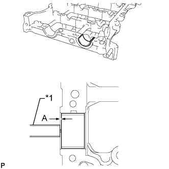
Text in Illustration *1 Vernier Caliper Using a vernier caliper, measure the distance between the camshaft housing edge and the camshaft bearing edge.
Standard distance 1.15 to 1.85 mm (0.0453 to 0.0728 in.)
-
-
INSTALL NO. 1 CAMSHAFT BEARING
-
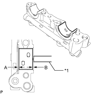
Text in Illustration *1 Vernier Caliper Clean the No. 1 camshaft bearing.
-
Install the camshaft bearing to the No. 1 camshaft bearing cap.
-
Using a vernier caliper, measure the distance between the camshaft bearing cap edge and the camshaft bearing edge.
Standard dimension A - B or B - A 0 to 0.7 mm (0 to 0.0276 in.)
-
-
INSTALL OIL CONTROL VALVE FILTER
-
Install the oil control valve filter to the No. 1 camshaft bearing cap.
-
-
INSTALL CAMSHAFT
-
Clean the camshaft journals, camshaft housing sub-assembly and camshaft bearing caps.
-
Apply a light coat of engine oil to the camshaft journals, camshaft housing sub-assembly and camshaft bearing caps.
-
Install the No. 1 camshaft and No. 2 camshaft to the camshaft housing sub-assembly.
-
-
INSTALL CAMSHAFT BEARING CAP
-
Confirm the marks and numbers on the camshaft bearing caps and place them in their proper positions and directions.
-
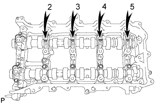
Install the 11 bolts in the order shown in the illustration.
- Torque:
- 16 N*m { 163 kgf*cm, 12 ft.*lbf }
Note
Make sure that the No. 1 camshaft and No. 2 camshaft rotate smoothly after installing the camshaft bearing caps.
-
-
INSTALL CAMSHAFT HOUSING SUB-ASSEMBLY
-
Text in Illustration *1 No. 1 Valve Rocker Arm Sub-assembly *2 Valve Stem Cap *3 Valve Lash Adjuster Assembly *a Incorrect *b Correct Check that the No. 1 valve rocker arm sub-assemblies are installed as shown in the illustration.
-
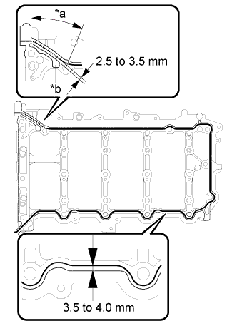
Text in Illustration *a Dashed Line *b Groove Apply seal packing in a continuous line as shown in the illustration.
Seal Packing Toyota Genuine Seal Packing Black, Three Bond 1207B or equivalent Apply Seal Packing as Follows Area Seal Packing Diameter Application Position Continuous Line 3.0 to 4.0 mm (0.118 to 0.157 in.) Distance from edge of camshaft housing sub-assembly to center of seal packing: 3.5 to 4.0 mm (0.138 to 0.157 in.) Dashed Line Distance from outside edge of groove to center of seal packing: 2.5 to 3.5 mm (0.0984 to 0.138 in.) Note
-
Remove any oil from the contact surface.
-
Install the camshaft housing sub-assembly within 3 minutes and tighten the bolts within 10 minutes after applying seal packing.
-
-
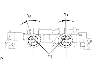
Text in Illustration *1 Knock Pin *a Approximately 17° *b Approximately 2° Position the knock pin of the No. 1 camshaft and No. 2 camshaft as shown in the illustration.
-
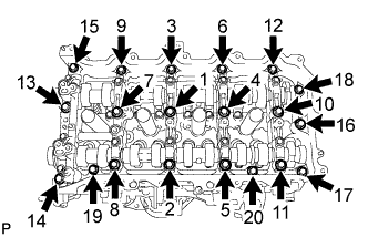
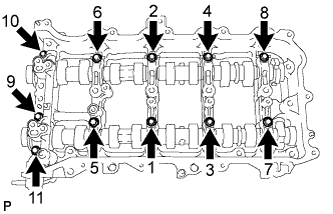
Install the camshaft housing sub-assembly, and then install the 20 bolts in the order shown in the illustration.
- Torque:
- 27 N*m { 275 kgf*cm, 20 ft.*lbf }
Note
-
Do not add engine oil for at least 4 hours after the installation.
-
Do not start the engine for at least 4 hours after the installation.
-
After installation, if the seal packing has seeped out, wipe if off.
-
-
INSTALL CAMSHAFT TIMING GEAR ASSEMBLY
-
Text in Illustration *a Knock Pin Hole *b Alignment Mark Check the camshaft timing gear assembly position.
If the camshaft timing gear assembly is not set to the advanced position, release the lock pin and reset the camshaft timing gear assembly (Refer to the "Set Camshaft Timing Gear Assembly" procedure).
-
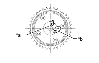
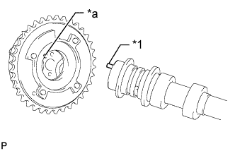
Text in Illustration *1 Knock Pin *a Knock Pin Hole Align and fit the knock pin of the No. 1 camshaft with the knock pin hole of the camshaft timing gear assembly.
-
Text in Illustration *1 Camshaft Timing Gear Assembly *2 Camshaft Flange *a Incorrect *b Correct *c Clearance *d No Clearance Check that there is no clearance between the camshaft timing gear assembly and camshaft flange.
-
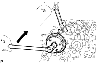
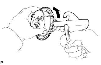
Text in Illustration *a Hold *b Turn Using a wrench to hold the hexagonal portion of the No. 1 camshaft, install the bolt.
- Torque:
- 85 N*m { 867 kgf*cm, 63 ft.*lbf }
Note
-
Be careful not to damage the cylinder head sub-assembly or spark plug tube with the wrench.
-
Do not disassemble the camshaft timing gear assembly.
-
-
INSTALL CAMSHAFT TIMING EXHAUST GEAR ASSEMBLY
-
Text in Illustration *1 Knock Pin *a Knock Pin Hole Align and fit the knock pin of the No. 2 camshaft with the knock pin hole of the camshaft timing exhaust gear assembly.
-
Text in Illustration *1 Camshaft Timing Exhaust Gear Assembly *2 Camshaft Flange *a Incorrect *b Correct *c Clearance *d No Clearance Check that there is no clearance between the camshaft timing exhaust gear assembly and camshaft flange.
-
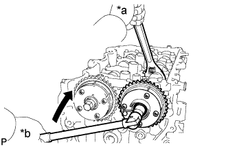
Text in Illustration *a Hold *b Turn Using a wrench to hold the hexagonal portion of the No. 2 camshaft, install the bolt.
- Torque:
- 85 N*m { 867 kgf*cm, 63 ft.*lbf }
Note
-
Be careful not to damage the cylinder head sub-assembly or spark plug tube with the wrench.
-
Do not disassemble the camshaft timing exhaust gear assembly.
-
-
ADD ENGINE OIL
-
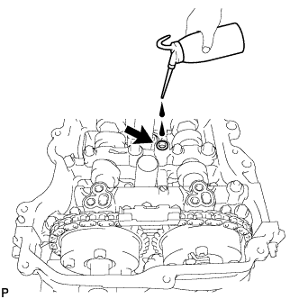
Add 50 cc (3.1 cu. in) of engine oil into the oil hole shown in the illustration.
Note
-
Oil must be added if the valve lash adjuster assemblies were removed.
-
Make sure that the low pressure chamber and oil paths of the valve lash adjuster assemblies are full of engine oil.
-
-
-
SET NO. 1 CYLINDER TO TDC/COMPRESSION
-
Temporarily install the crankshaft pulley bolt.
-
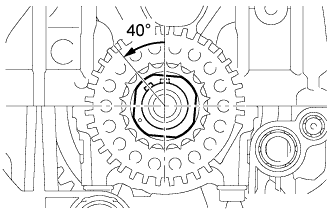
Rotate the crankshaft 40° counterclockwise to position the crankshaft pulley key as shown in the illustration.
-
Text in Illustration *a Approximately 7° *b Approximately 32° *c Timing Mark Check that the timing marks of the camshaft timing gear assembly and camshaft timing exhaust gear assembly are as shown in the illustration.
Tech Tips
"A" is not a timing mark.
-
-
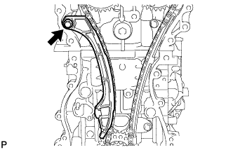
INSTALL NO. 1 CHAIN VIBRATION DAMPER
-
Install the No.1 chain vibration damper with the 2 bolts in the order shown in the illustration.
- Torque:
- 21 N*m { 214 kgf*cm, 15 ft.*lbf }
-
-
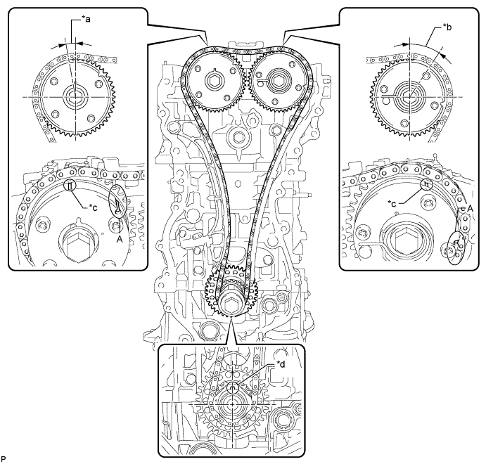
INSTALL CHAIN SUB-ASSEMBLY
-
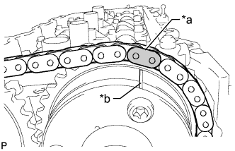
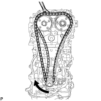
Place the chain sub-assembly onto the camshaft timing gear assembly, camshaft timing exhaust gear assembly and crankshaft timing sprocket.
Tech Tips
-
Make sure the mark plate of the chain sub-assembly faces away from the engine.
-
It is not necessary to install the chain sub-assembly to the teeth of the camshaft timing gear assembly, camshaft timing exhaust gear assembly and crankshaft timing sprocket.
-
-
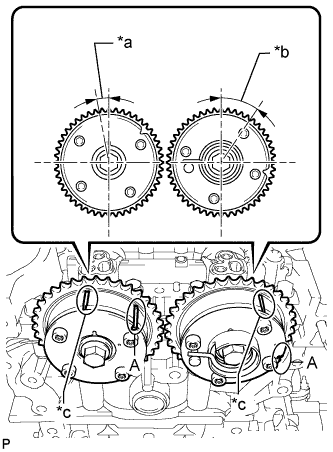
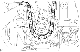
Text in Illustration *a Mark Plate *b Timing Mark Align the mark plate (yellow or gold) of the chain sub-assembly with the timing mark of the camshaft timing exhaust gear assembly and install the chain sub-assembly to the camshaft timing exhaust gear assembly.
-
Text in Illustration *a Mark Plate *b Timing Mark Align the mark plate (pink or gold) of the chain sub-assembly with the timing mark of the crankshaft timing sprocket and install the chain sub-assembly to the crankshaft timing sprocket.
-
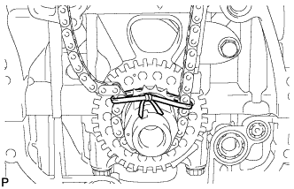
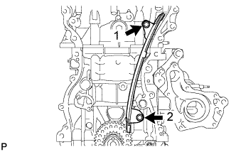
Tie a string above the crankshaft timing sprocket so that the chain sub-assembly is secure.
-
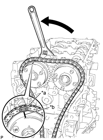
Text in Illustration *a Mark Plate *b Timing Mark Using a wrench, hold the hexagonal portion of the No. 1 camshaft, rotate the No. 1 camshaft counterclockwise, align the timing mark of the camshaft timing gear assembly with the mark plate (yellow or gold) of the chain sub-assembly and install the chain sub-assembly to the camshaft timing gear assembly.
Tech Tips
Hold the No. 1 camshaft in place with a wrench until the No. 1 chain tensioner assembly is installed.
-
Remove the string above the crankshaft timing sprocket, rotate the crankshaft clockwise, and loosen the chain sub-assembly so that the chain tensioner slipper can be installed.
Note
Make sure the chain sub-assembly is secure.
-
-
INSTALL CHAIN TENSIONER SLIPPER
-
Install the chain tensioner slipper with the bolt.
- Torque:
- 21 N*m { 214 kgf*cm, 15 ft.*lbf }
-
-
INSTALL NO. 1 CHAIN TENSIONER ASSEMBLY
-
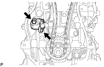
Install a new gasket and the No. 1 chain tensioner assembly with the 2 bolts.
- Torque:
- 10 N*m { 102 kgf*cm, 7 ft.*lbf }
-
Remove the pin from the stopper plate.
-
-
INSTALL TIMING CHAIN GUIDE
-
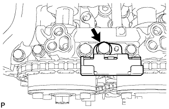
Install the timing chain guide with the bolt
- Torque:
- 21 N*m { 214 kgf*cm, 15 ft.*lbf }
-
-
CHECK NO. 1 CYLINDER TO TDC/COMPRESSION
-
Temporarily install the crankshaft pulley bolt.
Text in Illustration *a Approximately 7° *b Approximately 32° *c Timing Mark *d Crankshaft Pulley Key -
Rotate the crankshaft clockwise and align the crankshaft pulley key as shown in the illustration.
-
Check that the timing marks on the camshaft timing gear assembly and camshaft timing exhaust gear assembly are as shown in the illustration.
Tech Tips
"A" is not a timing mark.
-
Remove the crankshaft pulley bolt.
-
-
INSTALL TIMING CHAIN COVER SUB-ASSEMBLY